Blade, centrifugal fan and electrical equipment

A centrifugal fan and blade technology, used in mechanical equipment, machines/engines, liquid fuel engines, etc., can solve the problem of insufficient blade strength, and achieve the effects of improving strength, avoiding efficiency reduction and low noise

Pending Publication Date: 2020-12-11
GREE ELECTRIC APPLIANCES INC
View PDF0 Cites 1 Cited by
  • Summary
  • Abstract
  • Description
  • Claims
  • Application Information

AI Technical Summary

Problems solved by technology

[0003] Aiming at the problem of insufficient strength of existing blades, the present invention proposes a blade, a centrifugal fan and electrical equipment. The blade, centrifugal fan and electrical equipment can achieve the technical effects of large flow, low noise and high efficiency, and at the same time facilitate large Mass production of blades

Method used


Image

  • Blade, centrifugal fan and electrical equipment
  • Blade, centrifugal fan and electrical equipment
  • Blade, centrifugal fan and electrical equipment

Examples


Embodiment Construction

[0033] In order to make the above objects, features and advantages of the present invention more comprehensible, specific implementations of the present invention will be described in detail below in conjunction with the accompanying drawings. In the following description, numerous specific details are set forth in order to provide a thorough understanding of the present invention. However, the present invention can be implemented in many other ways different from those described here, and those skilled in the art can make similar improvements without departing from the connotation of the present invention, so the present invention is not limited by the specific embodiments disclosed below.

[0034] In describing the present invention, it should be understood that the terms "center", "longitudinal", "transverse", "length", "width", "thickness", "upper", "lower", "front", " Back", "Left", "Right", "Vertical", "Horizontal", "Top", "Bottom", "Inner", "Outer", "Clockwise", "Counte...


PUM


Abstract

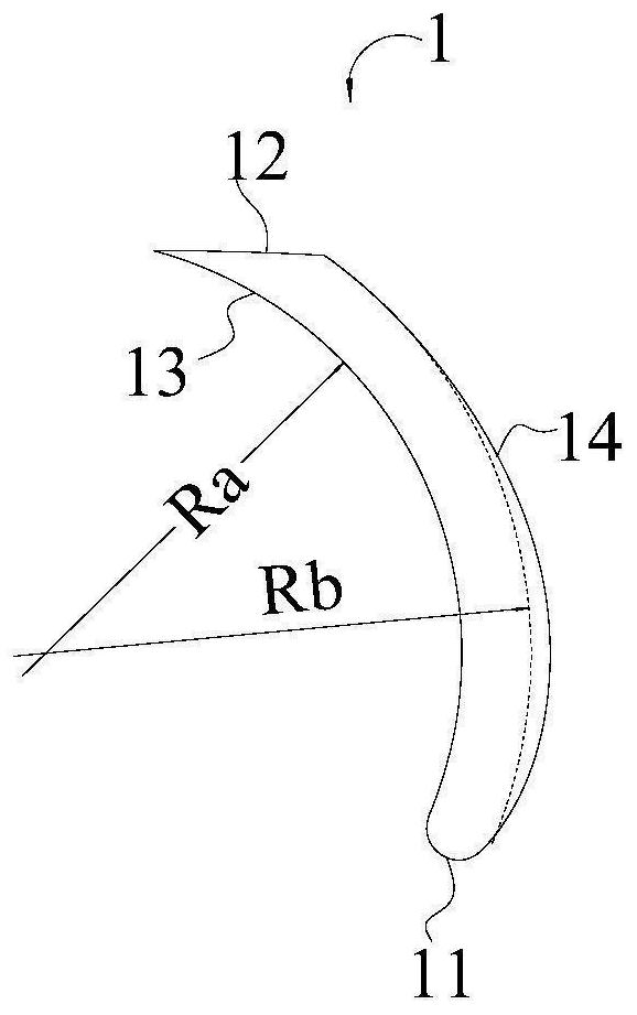
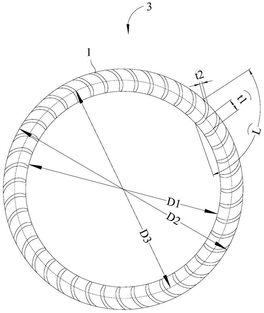
The invention relates to a blade, a centrifugal fan and electrical equipment. The thickness of the blade is gradually increased and then gradually decreased from one end of a tail edge 12 of the bladeto one end of a front edge 11 of the blade, and the thickness of the tail edge 12 of the blade is larger than 1.5 mm. The centrifugal fan comprises an impeller 3 and a plurality of blades arranged onthe impeller 3, wherein the plurality of blades are evenly distributed in the circumferential direction of the axis of the impeller 3, and the tail edge 12 of each blade is located on the outer diameter circle of the impeller 3. The blade, the centrifugal fan and the electrical equipment have the effects of high flow, low noise and high efficiency, meanwhile, the injection molding strength of theblade can be improved, and large-batch injection molding production of the blade is facilitated.

Description

technical field [0001] The invention relates to the technical field of centrifugal fans, in particular to a blade, a centrifugal fan and electrical equipment. Background technique [0002] The front edge, pressure surface, trailing edge and suction surface of the blade are connected end to end in sequence to form the blade of the fan, and the pressure surface is opposite to the suction surface. Most of the blades on the impeller of the existing centrifugal fan are designed according to the airfoil blade to improve the performance of the fan. However, when the blade is completely designed according to the airfoil blade, because the trailing edge of the blade is very thin, its strength is low and it is easy to break, which is not conducive to injection molding. In order to facilitate mass production, it will also result in reduced centrifugal fan efficiency, increased noise, and reduced flow. Contents of the invention [0003] Aiming at the problem of insufficient strength ...

Claims


Application Information

Patent Timeline
Patent Type & Authority Applications(China)
IPC IPC(8): F04D29/30F04D29/28F04D29/42F04D29/66
CPCF04D29/281F04D29/30F04D29/4233F04D29/666F04D29/667
Inventor 陈帆汤雁翔崔剑飞刘司轶朱国善
Owner GREE ELECTRIC APPLIANCES INC
Why Eureka
Try Eureka