
Internet of Things monitoring equipment for information acquisition

A technology for monitoring equipment and information collection, applied in mechanical equipment, supporting machines, machines/stands, etc., can solve the problems of inconvenient operation, time-consuming and laborious operation, wear and tear, etc., to meet the needs of users, simple and convenient operation, and adjustment range. big effect

Pending Publication Date: 2020-12-11
金花兰
View PDF6 Cites 2 Cited by
  • Summary
  • Abstract
  • Description
  • Claims
  • Application Information

AI Technical Summary

Problems solved by technology

[0003] In the layout of the Internet of Things, it is generally necessary to use the Internet of Things monitoring equipment for information collection. Most of the existing Internet of Things monitoring equipment is fixed on the wall with bolts. This fixing method has many disadvantages, such as When installing it, the operation is inconvenient, and tools such as screwdrivers or wrenches are required, and the operation is time-consuming and laborious. It is not easy to dismantle the IoT monitoring equipment later, so it is not convenient to repair the IoT monitoring equipment, and the bolts After repeated disassembly and assembly, there will be greater wear and tear, making the effect of fixing the IoT monitoring equipment not good, and it will become loose. Moreover, after the existing IoT monitoring equipment is fixed, many of them are easy to adjust the angle. Aiming at the deficiencies of existing technologies, we designed an IoT monitoring device for information collection to solve the above problems

Method used


Image

  • Internet of Things monitoring equipment for information acquisition
  • Internet of Things monitoring equipment for information acquisition
  • Internet of Things monitoring equipment for information acquisition

Examples


Embodiment 1

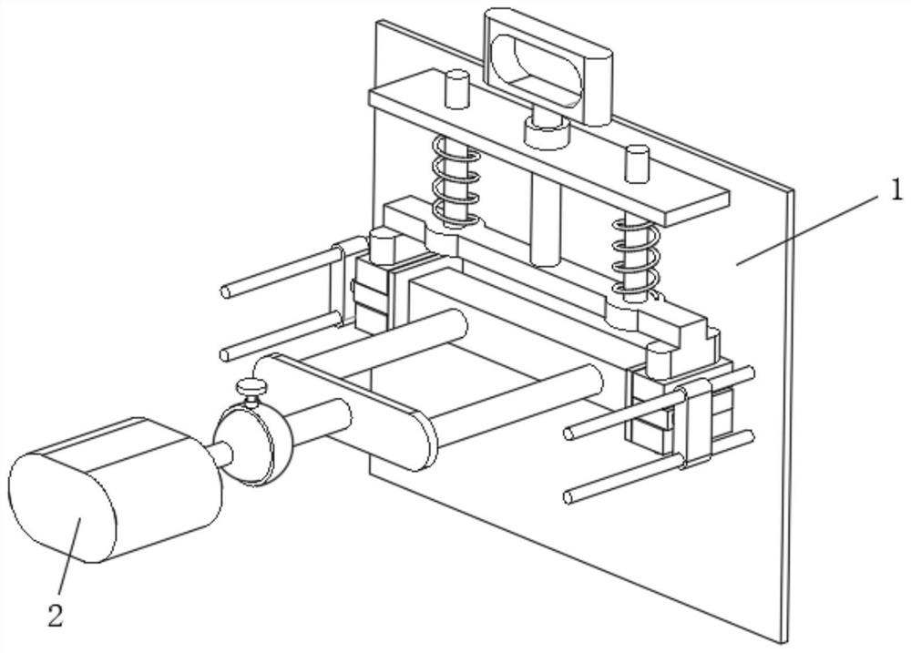
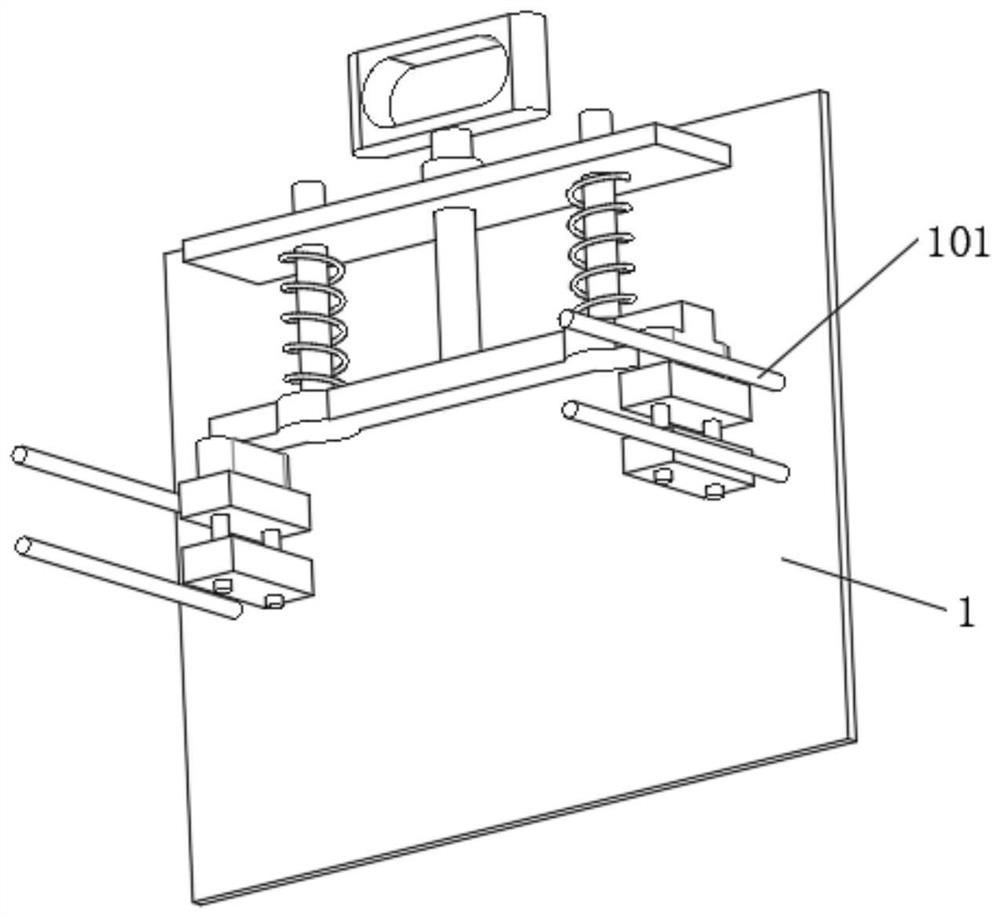
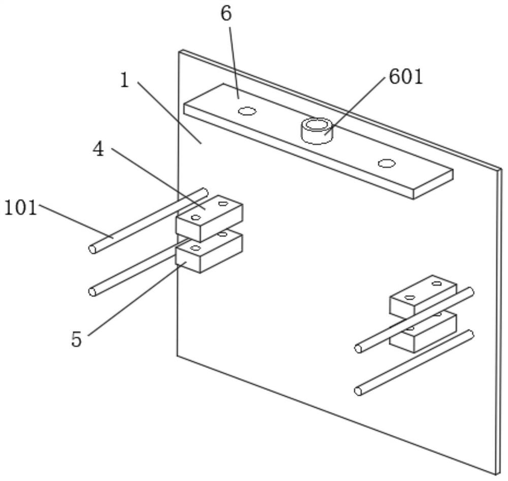
[0028] see Figure 1-7 As shown, an IoT monitoring device for information collection includes a wall panel 1, a monitoring device body 2 and a load-bearing block 3. The front of the load-bearing block 3 is fixedly connected with two sets of support columns 304, and the two sets of support columns 304 are far away from the load-bearing One end of the block 3 is fixedly connected with a support plate 305, and the support plate 305 is provided with an adjustment mechanism corresponding to the main body 2 of the monitoring equipment. The position plate 301, the side of the limit plate 301 away from the load-bearing block 3 is fixedly connected with a block 302, and the top of the block 302 is provided with two sets of locking holes 3021, and the side of the block 302 away from the limit plate 301 is fixedly connected to a limited Position block 303, the side wall of limit block 303 is provided with two sets of limit holes 3031, the front of wallboard 1 is fixedly connected with li...

Embodiment 2

[0035] see Figure 1-7 As shown, an IoT monitoring device for information collection includes a wall panel 1, a monitoring device body 2 and a load-bearing block 3. The front of the load-bearing block 3 is fixedly connected with two sets of support columns 304, and the two sets of support columns 304 are far away from the load-bearing One end of the block 3 is fixedly connected with a support plate 305, and the support plate 305 is provided with an adjustment mechanism corresponding to the main body 2 of the monitoring equipment. The position plate 301, the side of the limit plate 301 away from the load-bearing block 3 is fixedly connected with a block 302, and the top of the block 302 is provided with two sets of locking holes 3021, and the side of the block 302 away from the limit plate 301 is fixedly connected to a limited Position block 303, the side wall of limit block 303 is provided with two sets of limit holes 3031, the front of wallboard 1 is fixedly connected with li...


PUM


Abstract

The invention discloses Internet of Things monitoring equipment for information acquisition. A wallboard, a monitoring equipment body and a bearing block are included, two groups of supporting columnsare fixedly connected to the front surface of the bearing block, a supporting plate is fixedly connected to the ends, far away from the bearing block, of the two groups of supporting columns, and anadjusting mechanism corresponding to the monitoring equipment body is arranged on the supporting plate. The monitoring equipment body is fixedly installed on the front face of the supporting plate, limiting plates are fixedly connected to the two sides of the bearing block, clamping blocks are fixedly connected to the sides, away from the bearing block, of the limiting plates, two sets of lockingholes are formed in the tops of the clamping blocks, and limiting blocks are fixedly connected to the sides, away from the limiting plates, of the clamping blocks. The Internet of Things monitoring equipment has the beneficial effects that when a user installs and fixes the monitoring equipment body, the operation is simple and convenient, time and labor are saved, the monitoring equipment body isconveniently disassembled and overhauled in the later period, the operation is convenient, the monitoring equipment body is disassembled and assembled multiple times, and the monitoring equipment main body is also ensured to be fixed stably and not to loosen.

Description

technical field [0001] The invention relates to a monitoring device, in particular to an Internet of Things monitoring device for information collection, belonging to the technical field of the Internet of Things. Background technique [0002] The Internet of Things refers to the real-time collection of any object or process that needs to be monitored, connected, and interacted, and its sound, Various required information such as light, heat, electricity, mechanics, chemistry, biology, and location can be connected through various possible networks to realize the connection between objects and objects and between objects and people, and realize the intelligent perception of objects and processes, identification and management. [0003] In the layout of the Internet of Things, it is generally necessary to use the Internet of Things monitoring equipment for information collection. Most of the existing Internet of Things monitoring equipment is fixed on the wall with bolts. Th...

Claims


Application Information

Patent Timeline
Patent Type & Authority Applications(China)
IPC IPC(8): F16M13/02F16M11/14F16M11/16
CPCF16M11/14F16M11/16F16M13/02
Inventor 金花兰
Owner 金花兰
Learn More