
A readable measurement method for blade profile

A measurement method and blade technology, applied in the direction of mechanical counter/curvature measurement, measuring device, mechanical measuring device, etc., can solve the problems of low accuracy of multiple detection data of the blade profile, and the detection data cannot be obtained intuitively, so as to reduce the The effect of equipment maintenance cost, reduction of clamping time and improvement of data accuracy

Active Publication Date: 2022-02-01
CHINA HANGFA GUIZHOU LIYANG AVIATION POWER CO LTD
View PDF0 Cites 0 Cited by
  • Summary
  • Abstract
  • Description
  • Claims
  • Application Information

AI Technical Summary

Problems solved by technology

[0002] In the production of aerospace components, in order to reduce the cost of space launch and improve the performance of components, there will be many sheet metal parts with profiles; after the production of aeroengine blades is completed, the profiles of the blades need to be tested. Two types of inspection: one is the comparative detection of the blade body profile, and the other is the detection by three-coordinate or optical scanning equipment; the comparative detection of the blade body profile is mainly used for the blank and rough machining of the blade body profile Or the detection of the profile after semi-finishing is calculated and judged by measuring the gap between the profile and the standard sample and the side gap between the standard sample and the base of the measuring tool through a feeler gauge. Since the size of the gap is manually measured by a feeler gauge, the feeler gauge is inserted When there is a gap between the profile and the standard template, the small deformations of the profile and the standard template are different each time, and the accuracy of the multiple detection data of the blade profile is low, and the detection data cannot be obtained intuitively

Method used


Image

  • A readable measurement method for blade profile
  • A readable measurement method for blade profile
  • A readable measurement method for blade profile

Examples


Embodiment Construction

[0031] The technical solution of the present invention is further described below, but the scope of protection is not limited to the description.

[0032] see Figure 1 to Figure 4 shown.

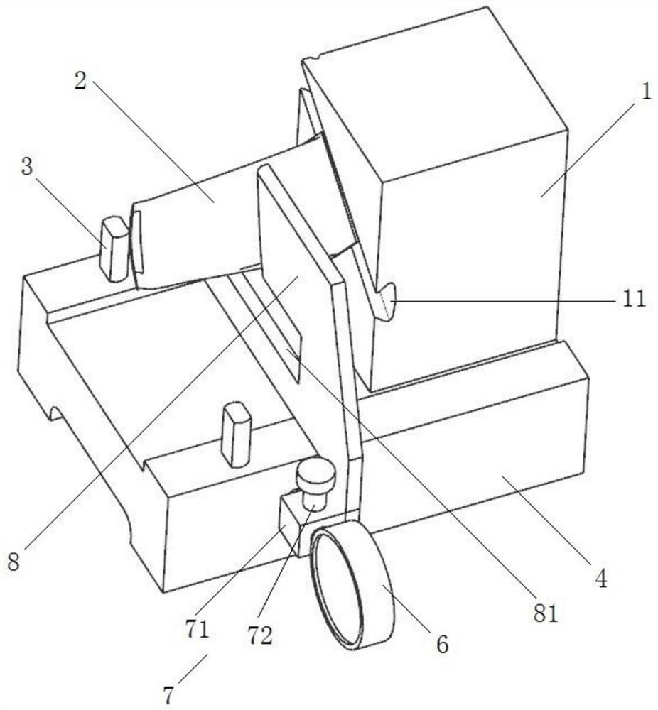
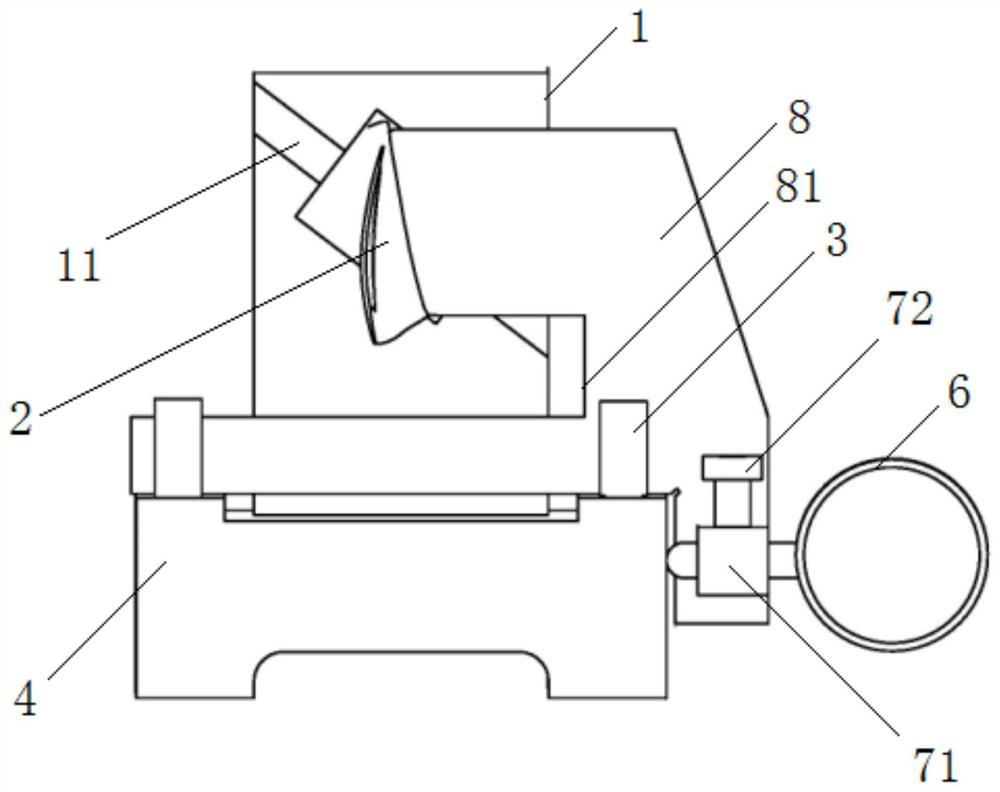
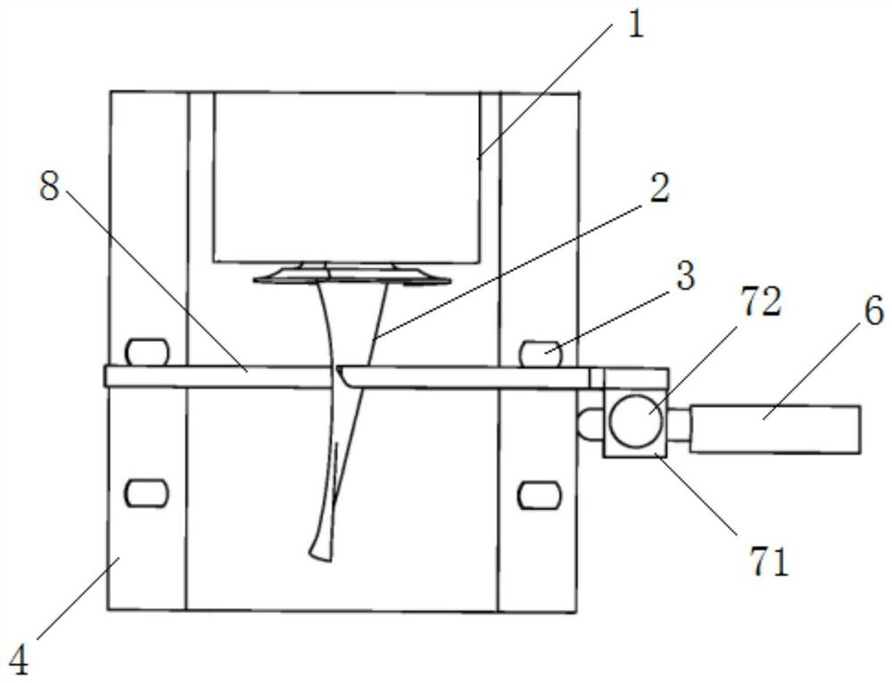
[0033] A measuring tool with readable blade profiles according to the present invention comprises: a base 4, a chuck 1 fixed on the top plane of the base 4, the front side of the chuck 1 is provided with a mounting groove 11 inclined to the top surface of the base 4, The root of the blade 2 is tightly clamped with the installation groove 11. When the front top side end surface of the profile template 8 is in contact with the profile line of the blade 2, the contact force between the profile template 8 and the blade 2 is horizontal, and the inclined installation groove 11 restricting the movement of the root of the blade 2 in the horizontal direction;

[0034] Section positioning pins 3, a plurality of section positioning pins 3 are fixed on both sides of the top surface of the base 4 with...


PUM


Abstract

The invention discloses a method for measuring the readable value of the profile of a blade, assuming that the upper difference of the contour of the profile of the blade to be measured is a 上 , the lower difference is a 下 , use a feeler gauge to measure the maximum gap between the profile template and the blade as b 最大 , the minimum gap is b 最小 , the gap c value reads the dial indicator; when c=0, and a 上 -a 下 ≥b 最大 , the profile of the blade profile is qualified; when the clearance c=0, and a 上 -a 下 <b 最大 , a 上 -a 下 >b 最小 , the profile of the blade profile is locally super-lower, unqualified; when c>0, at this time, b 最小 is 0, c‑b 最大 <a 下 -a 上 , the local super-lower difference of the profile of the blade profile b 最小 Super upper difference, c‑b 最大 >a 上 -a 下 The profile of the blade profile is poor overall, unqualified; when c>0, at this time b 最小 is 0, the maximum machining allowance of the blade profile is: c, and the minimum machining allowance is c‑b 最大 ; If c=0, there is no machining allowance for the blade; the measurement accuracy is guaranteed, and the problem of small deformation of the feeler gauge is solved.

Description

technical field [0001] The invention relates to a method for measuring the readable number of a blade profile, which belongs to the technical field of profile measurement. Background technique [0002] In the production of aerospace components, in order to reduce the cost of space launch and improve the performance of components, there will be many sheet metal parts with profiles; after the production of aeroengine blades is completed, the profiles of the blades need to be tested. Two types of inspection: one is the comparative detection of the blade body profile, and the other is the detection by three-coordinate or optical scanning equipment; the comparative detection of the blade body profile is mainly used for the blank and rough machining of the blade body profile Or the detection of the profile after semi-finishing is calculated and judged by measuring the gap between the profile and the standard sample and the side gap between the standard sample and the base of the m...

Claims


Application Information

Patent Timeline
Patent Type & Authority Patents(China)
IPC IPC(8): G01B5/20G01B5/00
CPCG01B5/20G01B5/003G01B5/0002G01B5/0004
Inventor 缪骏谷阿山徐华
Owner CHINA HANGFA GUIZHOU LIYANG AVIATION POWER CO LTD
Learn More