Brake pedal assembly

A brake pedal and assembly technology, which is applied in foot-operated starting devices, non-rotational vibration suppression, passenger/cab lighting, etc., can solve the problems that the brake pedal has no elasticity, cannot be easily disassembled and replaced, and the spring is prone to fatigue , to increase the stability of the

Pending Publication Date: 2020-12-15
YANGZHOU YONGRUI MACHINERY CO LTD
View PDF1 Cites 0 Cited by
  • Summary
  • Abstract
  • Description
  • Claims
  • Application Information

AI Technical Summary

Problems solved by technology

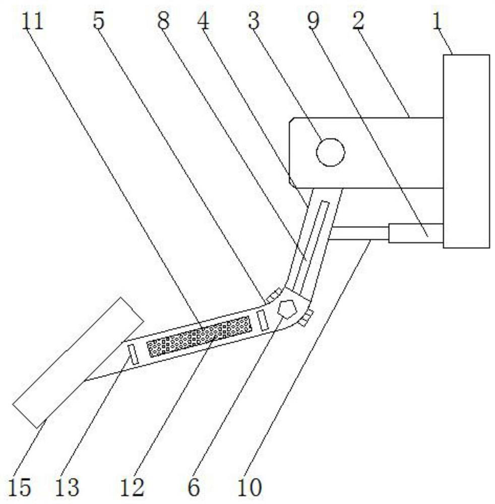
[0004] However, the existing brake pedal assembly cannot be easily disassembled and replaced, and when the feet are located at the rear of the brake pedal and the accelerator pedal, the feet are easily stuck, causing accidents. Not only that, the existing system The moving pedal adopts a torsion spring. After a long time of use, the spring is prone to fatigue, resulting in no elastic response of the brake pedal.

Method used


Image

  • Brake pedal assembly
  • Brake pedal assembly
  • Brake pedal assembly

Examples


Embodiment Construction

[0027] In order to make the technical means, creative features, goals and effects achieved by the present invention easy to understand, the present invention will be further described below in conjunction with specific embodiments.

[0028] In describing the present invention, it should be understood that the terms "upper", "lower", "front", "rear", "left", "right", "top", "bottom", "inner", " The orientation or positional relationship indicated by "outside", etc. is based on the orientation or positional relationship shown in the drawings, and is only for the convenience of describing the present invention and simplifying the description, rather than indicating or implying that the referred device or element must have a specific orientation, so as to Specific orientation configuration and operation, therefore can not be construed as limiting the present invention; in the description of the present invention, it should be noted that, unless otherwise clearly specified and limit...


PUM


Abstract

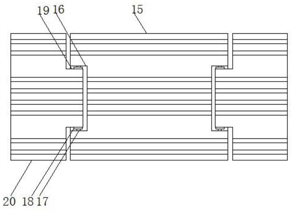
The invention relates to the technical field of brake pedal assemblies, and discloses a brake pedal assembly which comprises a fixing plate, and an anti-clamping pedal mechanism is arranged at the left side of the fixing plate; the anti-clamping pedal mechanism comprises a connecting plate, a first fixing rod, a first pedal rod, a second pedal rod, a main pedal plate, a groove, a second fixing rod, a torsion spring and an auxiliary pedal plate; and connecting plates are welded to the front end and the rear end of the left side of the fixing plate, and the first fixing rod is fixedly connectedbetween the two connecting plates. According to the brake pedal assembly, the groove, the fixing rods, the torsion spring and the limiting plate are arranged on the main pedal plate, the auxiliary pedal plate is connected to the main pedal plate and fixed to the fixing rods and the torsion spring, when the foot is located at the rear portion of a brake pedal and the rear portion of an acceleratorpedal, the auxiliary pedal plate can move forwards by lifting the foot, and the foot is prevented from being clamped; and meanwhile, through the arrangement of the limiting plate, when the main pedalplate and the auxiliary pedal plate are stepped on, the auxiliary pedal plate cannot move towards the rear side.

Description

technical field [0001] The invention relates to the technical field of brake pedal assemblies, in particular to a brake pedal assembly. Background technique [0002] Under normal circumstances, the driver will encounter a situation that requires braking to decelerate while driving. In this case, the most effective and direct action is to step on the brake pedal. Therefore, as one of the important parts of the car, the brake pedal assembly is an indispensable part of the vehicle braking system. The brake pedal assembly is installed in the cab, and is generally assembled on the front wall sheet metal or the bottom plate sheet metal. Although the shape and structure are different according to the design requirements, the main components are basically the same, mainly composed of the brake pedal and the brake pedal. The arm and other parts. [0003] Patent No. CN201610022348.X discloses a brake pedal assembly, including a brake pedal arm, a brake pedal installed at the tail of...

Claims


Application Information

Patent Timeline
Patent Type & Authority Applications(China)
IPC IPC(8): B60T7/06B60Q3/217F16F15/02
CPCB60T7/06B60Q3/217F16F15/02
Inventor 吴俊权
Owner YANGZHOU YONGRUI MACHINERY CO LTD
Why Eureka
Try Eureka