Fireproof door quick mounting structure

An installation structure and technology for fire doors, applied in the field of fire doors, can solve the problems of troublesome installation and time-consuming, and achieve the effects of easy cleaning, shortening installation time, and convenient and quick operation.

Active Publication Date: 2020-12-15
上海逸盾门业有限公司
View PDF5 Cites 3 Cited by
  • Summary
  • Abstract
  • Description
  • Claims
  • Application Information

AI Technical Summary

Problems solved by technology

[0004] The above existing technical solutions have the following defects: when installing the fire doors, according to the actual use needs of customers, the thickness of the fireproof materials is different, when the fireproof materials are placed between the first door panel and the second door panel, The contact areas of the first mounting plate and the second mounting plate will not be the same, so when opening the bolt holes on the first mounting plate and the second mounting plate, it is necessary to measure in advance to ensure that the first mounting plate and the second mounting plate Bolt holes are flush with each other, this operation takes a lot of time and installation is very troublesome

Method used


Image

  • Fireproof door quick mounting structure
  • Fireproof door quick mounting structure
  • Fireproof door quick mounting structure

Examples


Embodiment 1

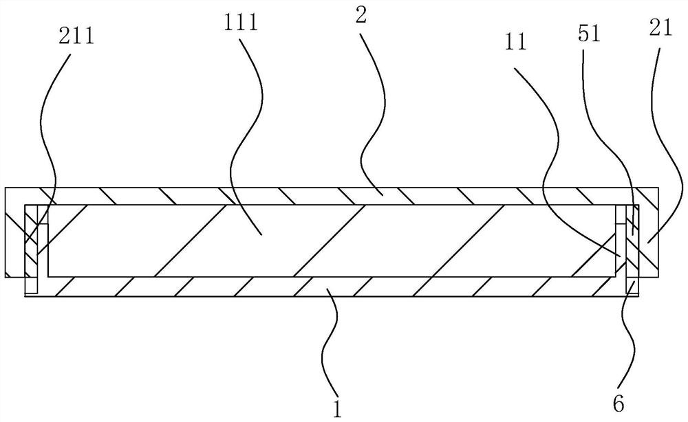
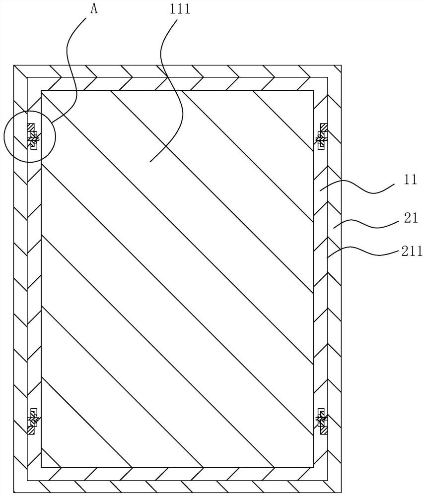
[0037] refer to Figure 1 to Figure 4, is a quick installation structure for a fireproof door disclosed in the present application, including a first door panel 1 and a second door panel 2, the first door panel 1 and the second door panel 2 are arranged parallel to each other, and the first door panel 1 faces one side of the second door panel 2 The first installation plate 11 is arranged symmetrically by bending, the length direction of the first installation plate 11 is arranged along the length direction of the first door panel 1, and the second door panel 2 is provided with a second door panel 2 facing the side of the first door panel 1 through bending. Mounting plate 21, the length direction of the second mounting plate 21 is arranged along the length direction of the second door panel 2; Between the second mounting plate 21, form a connection groove 211 for the insertion of the first mounting plate 11, the inner side wall of the connection groove 211 and The outer sidewal...

Embodiment 2

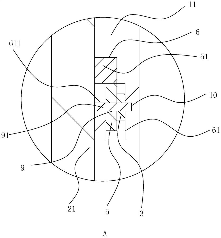
[0044] refer to Figure 5 , the embodiment of the present application also discloses a quick installation structure for a fire door. The length direction is set along the height direction of the first mounting plate 11, the first mounting groove 112 is provided with a rivet 10, the rivet 10 can slide in the first mounting groove 112, and the second mounting plate 21 is symmetrically provided with a rivet 10 Insert and slide the second mounting groove 212, the length direction of the second mounting groove 212 is set along the length direction of the second mounting plate 21; when installing between the first mounting plate 11 and the second mounting plate 21, the The rivet 10 is inserted into the first installation groove 112 and the second installation groove 212 at the same time, and according to the actual bonding degree of the first installation board 11 and the second installation board 21, the rivet 10 can be inserted between the first installation board 11 and the secon...


PUM


Abstract

The invention relates to a fireproof door quick mounting structure. The technical scheme of the fireproof door quick mounting structure is that fixing devices are arranged on a first mounting plate and a second mounting plate; each fixing device comprises a ratchet wheel, a pawl, a steel ring, a gear and a rack; a sliding groove allowing the rack to be inserted is formed in the end part of the first mounting plate; a locking groove is formed in the inner side wall of the sliding groove; the ratchet wheel is rotationally arranged in the locking groove; the pawl is hinged into the locking groove; the end part of the pawl is matched with the ratchet wheel; one end of the steel ring is fixed to the outer side wall of the pawl; the other end of the steel ring abuts against the inner wall of thelocking groove; the gear is fixedly arranged on the outer side wall of the ratchet wheel; the ratchet wheel and the gear are coaxially arranged; and the rack is matched with the gear. The fireproof door quick mounting structure has the effects that the fireproof door can be conveniently and rapidly mounted, and the requirements of fireproof materials with different thicknesses are met.

Description

technical field [0001] The present application relates to the technical field of fire doors, in particular to a quick installation structure for fire doors. Background technique [0002] At present, fire doors refer to doors that meet the requirements of fire resistance stability, integrity and heat insulation within a certain period of time. [0003] The structure of the fire doors on the existing market is often relatively simple. Referring to the figure, it includes a first door panel and a second door panel. And the second installation board is formed by bending around it, and the first installation board can be inserted between the second installation boards; when installing the fire door, the first installation of placing the fireproof material on the first door board Between the plates, then the second mounting plate on the second door plate is sleeved on the outside of the first mounting plate, and then the second mounting plate and the first mounting plate are fixe...

Claims


Application Information

Patent Timeline
Patent Type & Authority Applications(China)
IPC IPC(8): E06B5/16E06B3/70E06B7/28
CPCE06B5/16E06B3/7015E06B7/28
Inventor 姚少鹏夏磊李豪杨洪先夏献杰
Owner 上海逸盾门业有限公司
Why Eureka
Try Eureka