Micro turbojet engine combustion chamber structure

A turbojet engine and combustion chamber technology, which is applied in the field of aero-engines, can solve the problem of high temperature, and achieve the effects of improving combustion stability, good combustion effect and space utilization.

Pending Publication Date: 2020-12-15
TSINGHUA UNIV
View PDF0 Cites 1 Cited by
  • Summary
  • Abstract
  • Description
  • Claims
  • Application Information

AI Technical Summary

Problems solved by technology

[0005] The embodiment of the present application provides a micro-turbojet engine combustion chamber configuration, which aims to solve the problem of high wall temperature of the inner cylinder of the flame cylinder and the outer cylinder of the flame cylinder, so as to prolong the service life of the combustion chamber

Method used


Image

  • Micro turbojet engine combustion chamber structure
  • Micro turbojet engine combustion chamber structure
  • Micro turbojet engine combustion chamber structure

Examples


Embodiment Construction

[0030] The following will clearly and completely describe the technical solutions in the embodiments of the present application with reference to the drawings in the embodiments of the present application. Obviously, the described embodiments are part of the embodiments of the present application, not all of them. Based on the embodiments in this application, all other embodiments obtained by persons of ordinary skill in the art without creative efforts fall within the protection scope of this application.

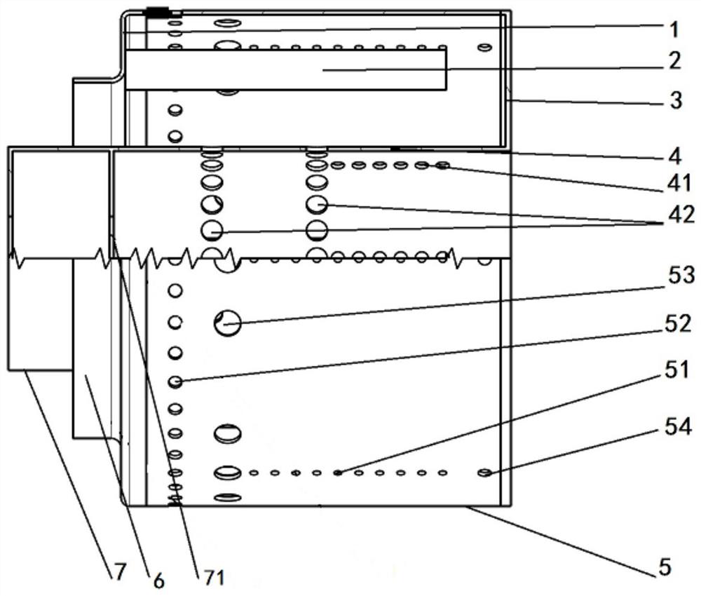
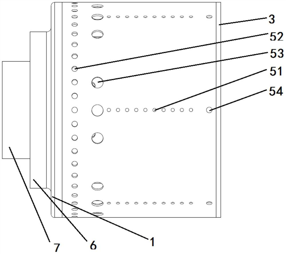
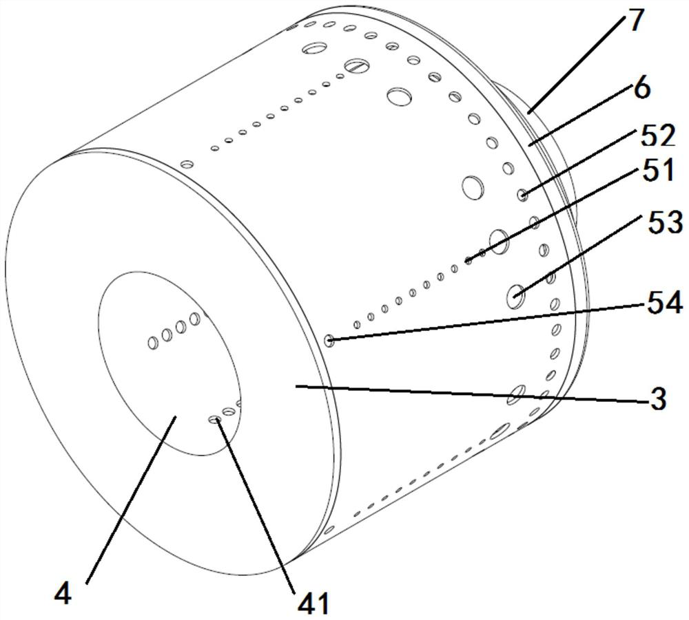
[0031] In related technologies, the combustion chamber of a micro turbojet engine (Micro Turbine Engine, MTE) with a thrust less than 100 daN generally uses an evaporator tube to supply fuel. , afterburning zone and mixing zone, such a design is very beneficial to the combustion organization in the combustion chamber of a large aero turbine engine. However, due to the very limited size of the MTE combustion chamber, the design of the combustion chamber of a large aero engin...


PUM


Abstract

The invention provides a micro turbojet engine combustion chamber structure. The micro turbojet engine combustion chamber structure comprises a flame tube outer cylinder and an evaporation pipe fixingplate, wherein the flame tube outer cylinder is arranged outside a flame tube inner cylinder in a sleeving mode, and a combustion chamber is formed between the flame tube inner cylinder and the flametube outer cylinder; air inlet hole sets are formed in the flame tube inner cylinder and the flame tube outer cylinder; the evaporation pipe fixing plate is connected to one end, far away from a first end cover, of the flame tube outer cylinder, an evaporation pipe is arranged inside the combustion chamber, and the evaporation pipe is close to the inner wall of the flame tube inner cylinder; andthe air inlet hole sets comprise a plurality of second through holes, the second through holes are formed in the flame tube outer cylinder which is located at the same angle as the evaporation pipe, and the straight line formed by connecting the multiple second through holes which are located at the same angle as the evaporation pipe is parallel to the axis of the evaporation pipe. The second through holes which are formed in the flame tube outer cylinder and directly face the evaporation pipe are formed, and when pressurized air enters the combustion chamber through the multiple second through holes, the air is blocked by the evaporation pipe to form airflow flowing along the wall surface, and therefore the inner wall of the flame tube outer cylinder is cooled and protected.

Description

technical field [0001] The present application relates to the technical field of aero-engines, in particular to a configuration of a combustion chamber of a micro-turbojet engine. Background technique [0002] The structure of a turbojet engine is composed of an intake port, a compressor, a combustion chamber, a turbine and an exhaust nozzle, wherein air enters the engine through the intake port, and the air is pressurized by the compressor, and the pressurized air enters the combustion chamber. The temperature is raised through the combustion chamber, and the high-temperature and high-pressure gas flowing out of the combustion chamber flows through the turbine and the tail nozzle, and finally sprays out from the tail nozzle. [0003] In related technologies, the combustion chamber of a micro turbojet engine (Micro Turbine Engine, MTE) with a thrust less than 100 daN generally uses an evaporator tube to supply fuel. , afterburning zone and mixing zone, such a design is very...

Claims


Application Information

Patent Timeline
Patent Type & Authority Applications(China)
IPC IPC(8): F23R3/38
CPCF23R3/38
Inventor 兰旭东李东杰周明周伯豪潘春雨梁骞李豪闫慧慧张煜洲
Owner TSINGHUA UNIV
Why Eureka
Try Eureka