Supercharge Your Innovation With Domain-Expert AI Agents!

Oscillator changing along with power supply voltage and chip

A power supply voltage, power supply voltage detection technology, applied in the direction of power oscillators, electrical components, etc., to achieve the effect of meticulous adjustment of the oscillation frequency

Pending Publication Date: 2020-12-15
XTX TECH INC
View PDF0 Cites 0 Cited by
  • Summary
  • Abstract
  • Description
  • Claims
  • Application Information

AI Technical Summary

Problems solved by technology

[0006] The purpose of the present invention is to provide an oscillator and chip that varies with the power supply voltage, aiming to solve the problem that the existing power supply voltage detection circuit only has one circuit and cannot increase or decrease the bias voltage of NMOS and PMOS. problem of control

Method used


Image

  • Oscillator changing along with power supply voltage and chip
  • Oscillator changing along with power supply voltage and chip
  • Oscillator changing along with power supply voltage and chip

Examples


Embodiment Construction

[0030] The following will clearly and completely describe the technical solutions in the embodiments of the present application with reference to the accompanying drawings in the embodiments of the present application. Obviously, the described embodiments are only some of the embodiments of the present application, not all of them. The components of the embodiments of the application generally described and illustrated in the figures herein may be arranged and designed in a variety of different configurations. Accordingly, the following detailed description of the embodiments of the application provided in the accompanying drawings is not intended to limit the scope of the claimed application, but merely represents selected embodiments of the application. Based on the embodiments of the present application, all other embodiments obtained by those skilled in the art without making creative efforts belong to the scope of protection of the present application.

[0031] It should ...


PUM


Abstract

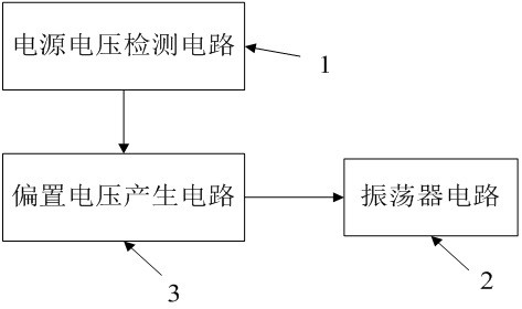
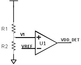
The invention discloses an oscillator changing along with a power supply voltage and a chip. At least two power supply voltage detection circuits are arranged, control can be realized through startingor closing a corresponding mirror image current module according to the change degree of the power supply voltage detected by the power supply voltage detection circuits, so as to adjust the oscillation frequency of the oscillator according to actual requirements, and adjust the oscillation frequency of the oscillator more meticulously.

Description

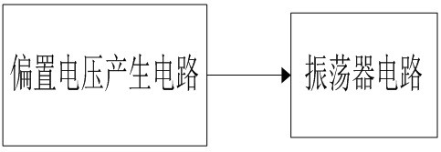
technical field [0001] The invention relates to the technical field of analog circuits, in particular to an oscillator and a chip that vary with power supply voltage. Background technique [0002] figure 1 As a traditional oscillator architecture, it consists of a bias voltage generating circuit and an oscillator circuit. An NMOS bias voltage and a PMOS bias voltage are generated by the bias voltage generating circuit; the ring oscillator of the oscillator circuit controls the frequency of the oscillator through the NMOS bias voltage and the PMOS bias voltage. [0003] The disadvantages of the traditional circuit are: when the power supply voltage changes, the bias voltage of the NMOS and the bias voltage of the PMOS will also change accordingly; when the bias voltage of the NMOS increases or the bias voltage of the PMOS decreases, the ring oscillator When the current increases, the charging and discharging time becomes shorter, that is, the cycle of the ring oscillator be...

Claims


Application Information

Patent Timeline
Patent Type & Authority Applications(China)
IPC IPC(8): H03B5/04H03B5/12
CPCH03B5/04H03B5/12
Inventor 徐明揆刘梦
Owner XTX TECH INC
Features
  • R&D
  • Intellectual Property
  • Life Sciences
  • Materials
  • Tech Scout
  • Unparalleled Data Quality
  • Higher Quality Content
  • 60% Fewer Hallucinations
Learn More