Grass trimmer and grass trimming head thereof

A technology for mowers and mowers, which is applied to lawn mowers, harvesters, agricultural machinery and implements, etc. It can solve the problems that affect the user's operation convenience, cannot adapt to the complicated working conditions of the mower, and are too long. , to achieve the effect of improving reliability and convenience of use

Active Publication Date: 2020-12-18
NANJING CHERVON IND
View PDF8 Cites 0 Cited by
  • Summary
  • Abstract
  • Description
  • Claims
  • Application Information

AI Technical Summary

Problems solved by technology

And for some lawn trimmers with automatic pay-off function in the prior art, it is set to when the grass trimmer is turned on and off, a speed difference will also be generated between the head shell and the spool to realize the pay-off, it cannot According to the actual needs, effective and reliable setting-out is carried out. On the premise that the cutting rope itself has an effective cutting length, this kind of setting-out requires the user to cut off the excess cutting rope, which actually causes a certain degree of waste of resources. And it will cause some unnecessary troubles to the user in the actual operation process, seriously affecting the convenience of the user's operation
[0004] Some documents also disclose that a sensor is installed inside the mowing head to sense the length of the mowing rope and transmit the signal to the control part to control the acceleration or deceleration of the mowing head. It also requires the mowing head There is a large speed difference, and the speed difference is generally required to be more than 30%. However, the grass cutting head that senses the signal through the sensor and controls the wire release has not been reflected in the existing products, and it has been proved by many parties in practice. In the process of paying off the wire, there will generally be situations where the wire cannot be paid out or the wire is too long, and its reliability is extremely poor, and it cannot adapt to the more complicated working conditions of the mower.

Method used


Image

  • Grass trimmer and grass trimming head thereof
  • Grass trimmer and grass trimming head thereof
  • Grass trimmer and grass trimming head thereof

Examples


Embodiment Construction

[0032] The present invention will be specifically introduced below in conjunction with the accompanying drawings and specific embodiments.

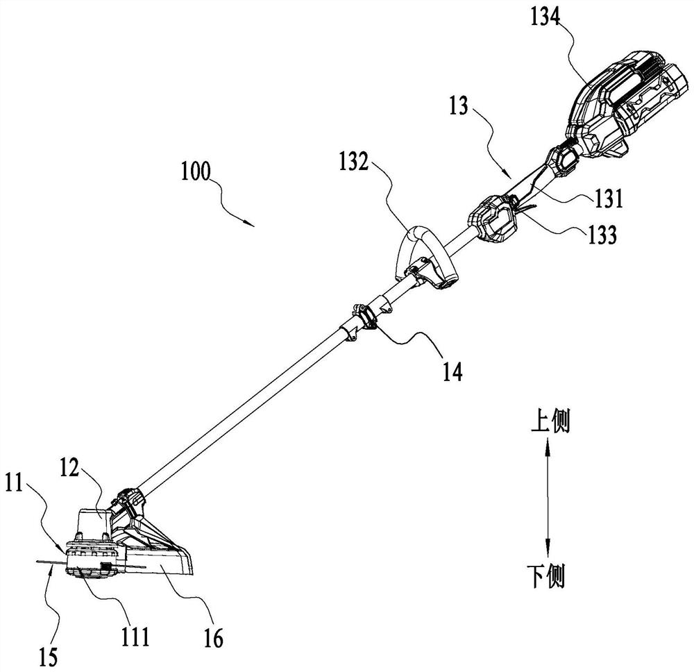
[0033] figure 1 The shown mowing machine 100 includes: a mowing head 11 , a driving device 12 , an operating device 13 and a connecting device 14 .

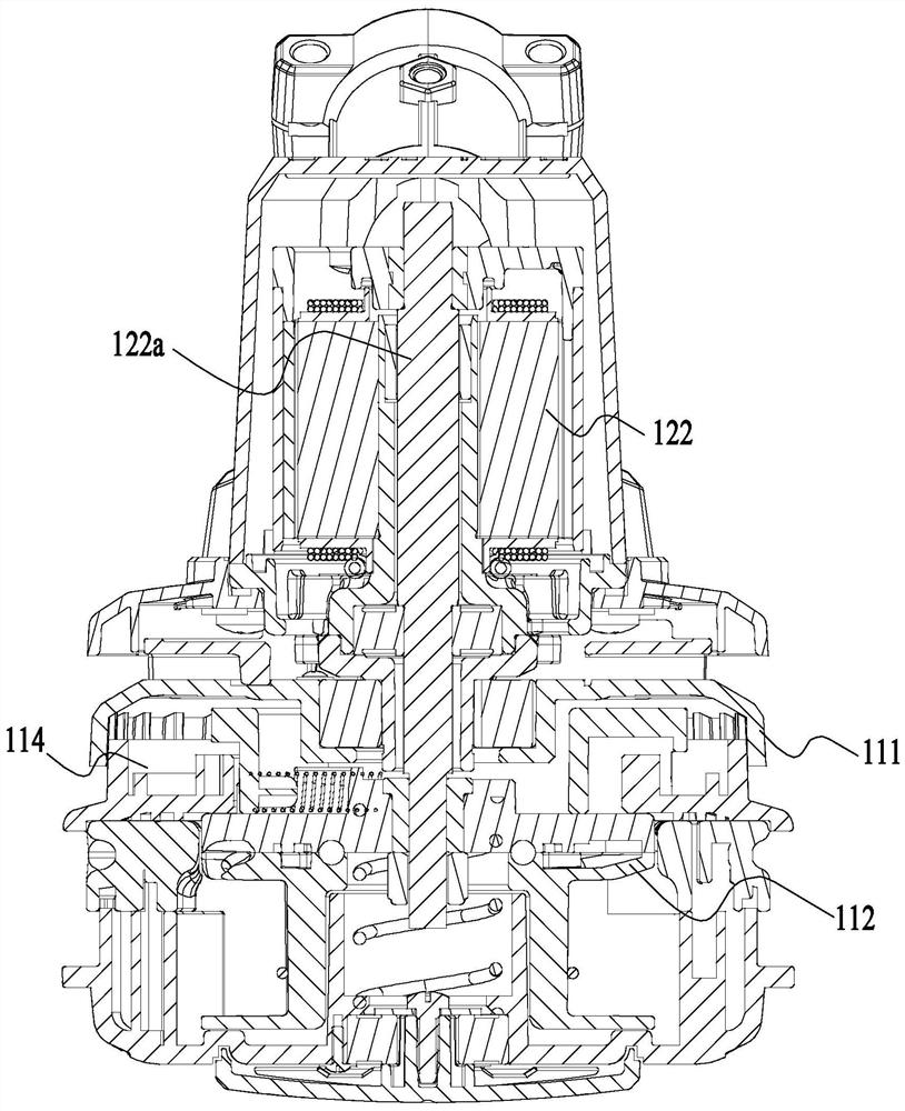
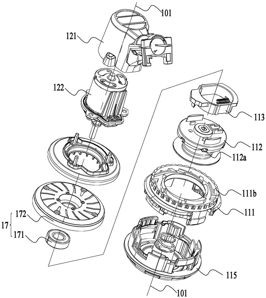
[0034] Such as Figure 1 to Figure 2As shown, the mowing head 11 is used to install the mowing rope 15 to realize the mowing function. The driving device 12 is used to provide rotational power to the mowing head 11. The driving device 12 includes a motor 122 and a first housing 121. The motor 122 is arranged in the first housing 121. The motor 122 drives the mowing head 11 to rotate the axis 101. for axis rotation. The operating device 13 includes: a handle 131 , an auxiliary handle 132 , a main switch 133 and a second housing 134 . The handle 131 and the auxiliary handle 132 are used to be held by both hands of the user, so that the mower 100 can be operated more stably. The main switc...


PUM


Abstract

The invention discloses a grass trimmer and a grass trimming head thereof. The grass trimmer comprises the grass trimming head and a motor; the grass trimming head comprises a spool, a head shell anda transmission piece, wherein the transmission piece has a first position and a second position relative to the spool; when the transmission piece is located at the first position, the grass trimminghead is in a working state; when the transmission piece is located at the second position, the grass trimming head is in an automatic paying-off state; and the barycenter of the transmission piece isdeviated from a rotating axis, when the grass trimming head is driven by the motor to rotate, the transmission piece is subjected to centrifugal force enabling the transmission piece to have the movement trend from the first position to the second position, and when the head shell rotates around the rotating axis, the head shell also applies resistance to the transmission piece against centrifugalforce to prevent movement of the transmission piece from the first position toward the second position. According to the grass trimmer, automatic paying off can be achieved when the length of the grass trimming rope is shortened to a certain length, paying off conditions do not need to be judged manually, and paying off reliability and use convenience are greatly improved.

Description

technical field [0001] The invention relates to a garden tool, in particular to a grass trimmer and a grass trimmer. Background technique [0002] As a garden tool, the lawn trimmer is especially suitable for trimming grasses such as villa lawns and garden lawns. At present, the grass trimmers on the market mainly use tapping to pay off the wire or control the spool of the grass trimming head and the head shell through a switch to generate a differential speed to pay off the wire. For the user, for the mowing machine in the prior art, the user cannot accurately release the length of the mowing rope according to actual needs. In fact, the grass trimmers in the prior art cannot realize automatic wire-releasing in the true sense. [0003] Generally speaking, the mowing head with the function of automatic pay-off generally makes the mowing rope be released by making relative rotation between the head shell and the spool. There are various ways to make the head shell and the s...

Claims


Application Information

Patent Timeline
Patent Type & Authority Applications(China)
IPC IPC(8): A01D34/416A01D69/06A01D75/20
CPCA01D34/416A01D69/06A01D75/20A01D34/4166A01D34/4162A01D2101/00
Inventor 郭建朋
Owner NANJING CHERVON IND
Why Eureka
Try Eureka