Mirror cabinet for smart home

A smart home and mirror cabinet technology, applied in home appliances, applications, mirrors, etc., can solve the problems of not being able to quickly and accurately take out items, inconvenient operation, and less frequent observation of makeup on both sides of the cheeks, etc., to increase the flexibility of use, Improve stability, good effect of use

Inactive Publication Date: 2020-12-18
台州正铭智能家居科技有限公司
View PDF1 Cites 1 Cited by
  • Summary
  • Abstract
  • Description
  • Claims
  • Application Information

AI Technical Summary

Problems solved by technology

[0003] In the mirror cabinet with the Chinese patent application number CN201910383834.8, the position of the connection and fixing plate of the side glass that is turned outward relative to the center glass in the prior art is changed, so that the side glass is turned towards the direction of the center glass, In this structure, there may be an angle between the side glass and the center glass, which is convenient for personnel to observe the makeup on both sides of the cheeks, but in actual use, the number of times to observe the makeup on both sides of the cheeks is relatively small, and the way the lenses are opened makes personnel When looking in the mirror, the lens will block the items inside the mirror cabinet, and personnel cannot quickly and accurately take out the required items, and when taking out the items, the hand needs to bypass the edge of the lens, which is inconvenient to operate

Method used


Image

  • Mirror cabinet for smart home
  • Mirror cabinet for smart home
  • Mirror cabinet for smart home

Examples


specific Embodiment approach

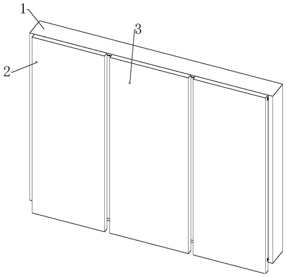
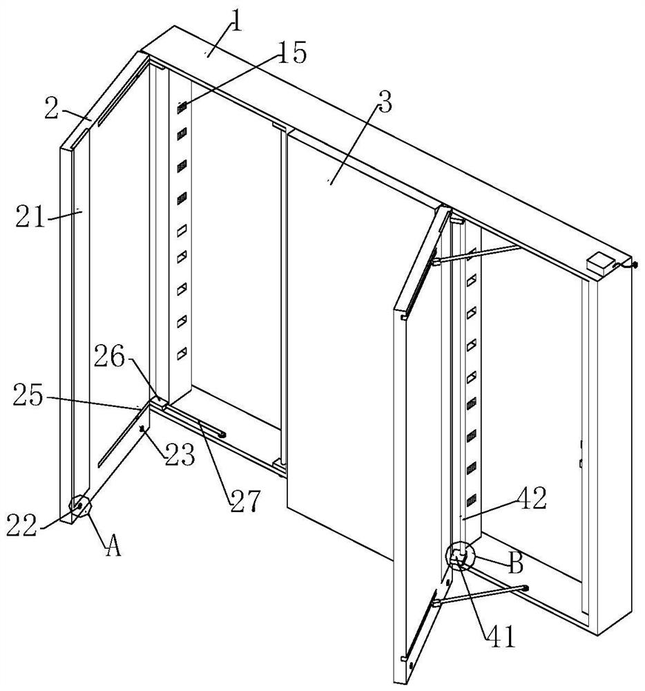
[0033] The specific embodiment: the cabinet body 1 is connected with the first mirror 2 through the rotating rod 27, the connecting block 26 and the slider 25, as figure 2 As shown, two opening methods are shown. One is to use the connecting hinge of the connecting block 26 and the sliding block 25 as a pivot point to make the first lens 2 rotate and open in a direction away from the second lens 3, and set it as the outer The other way is to use the end of the first lens 2 close to the second lens 3 as the pivot point, so that the first lens 2 is turned and opened towards the direction close to the second lens 3, which is set as the inward opening mode. There may be an included angle between the second lens 3 and the first lens 2, so that it is convenient for personnel to observe the makeup on the front and both sides of the cheek from the second lens 3 and the first lens 2, and the outward opening method is convenient for personnel to take the cabinet 1. The internal items a...


PUM


Abstract

The invention relates to the technical field of smart home, and particularly relates to a mirror cabinet for smart home. The mirror cabinet comprises a first lens, a connecting block, a sliding blockand a second lens, wherein the first lens can be opened in two modes, one mode is that a connecting hinge of the connecting block and the sliding block is used as a rotating hinge point, so that the first lens is rotatably opened in the direction away from the second lens, and the mode is set as an outward opening mode; the other mode is that one end, close to the second lens, of the first lens isused as a rotating hinge point, so that the first lens is rotatably opened in the direction close to the second lens, and the mode is set as an inward opening mode; an included angle can exist between the second lens and the first lens in the inward opening mode, so that people can conveniently observe the makeup of the front face and the two side faces of the cheek from the second lens and the first lens; and the outward opening mode is convenient for people to take articles in the cabinet body, and is suitable for daily mirror and article taking; and the double-opening type first lens increases the use flexibility, and the use effect is good.

Description

technical field [0001] The invention is a smart home mirror cabinet, which belongs to the technical field of smart home. Background technique [0002] A mirror cabinet is a cabinet equipped with a mirror, which not only has a storage function, but also allows users to reflect their appearance to organize their appearance and dress. A common mirror cabinet has one whole piece, two pieces or three pieces of lenses. In a mirror cabinet with more than two pieces of lenses, the turning and opening directions of the lenses are opposite, and it is difficult for the lenses to form a stable angle with each other. [0003] In the mirror cabinet with the Chinese patent application number CN201910383834.8, the position of the connection and fixing plate of the side glass that is turned outward relative to the center glass in the prior art is changed, so that the side glass is turned towards the direction of the center glass, In this structure, there may be an angle between the side gla...

Claims


Application Information

Patent Timeline
Patent Type & Authority Applications(China)
IPC IPC(8): A47B67/00A47B57/10A47B96/02A47G1/04E06B3/36E05C19/16E05D11/10B01D53/28
CPCA47B57/10A47B67/005A47B96/02A47G1/04B01D53/261B01D53/28E05C19/166E05D11/10E06B3/367
Inventor 孙艳婷热娜古丽·麦合木提王晓辉
Owner 台州正铭智能家居科技有限公司
Why Eureka
Try Eureka