A construction waste treatment equipment

A technology for waste disposal equipment and construction, applied in grain processing, packaging, cleaning methods and utensils, etc., can solve the problems of wasting resources, increasing costs, and taking a long time, so as to improve work efficiency, reduce labor intensity, and speed up crushing speed effect

Active Publication Date: 2022-07-15
山东方泰建业有限公司
View PDF0 Cites 0 Cited by
  • Summary
  • Abstract
  • Description
  • Claims
  • Application Information

AI Technical Summary

Problems solved by technology

[0002] With the development of my country's economy and the acceleration of urban and rural construction, some construction waste will inevitably be generated when demolishing buildings, such as cement, stones, nuts, screws, screws, gaskets, welding slag and welding rods accidentally discarded during maintenance. Wait, most of them are mixed together. Some iron nails and short steel bars can be reused. They are mixed in the construction waste. It is difficult to sort them out and it will take a long time. Generally, the staff will crush them together as construction waste and then separate them. For other purposes, this not only increases the difficulty of crushing construction waste, but also wastes resources
Existing processing devices are generally unable to recycle iron filings, which increases the cost, so it is urgent to make a construction waste processing equipment

Method used


Image

  • A construction waste treatment equipment
  • A construction waste treatment equipment
  • A construction waste treatment equipment

Examples


Embodiment Construction

[0040] A specific embodiment of the present invention will be described in detail below with reference to the accompanying drawings, but it should be understood that the protection scope of the present invention is not limited by the specific embodiment.

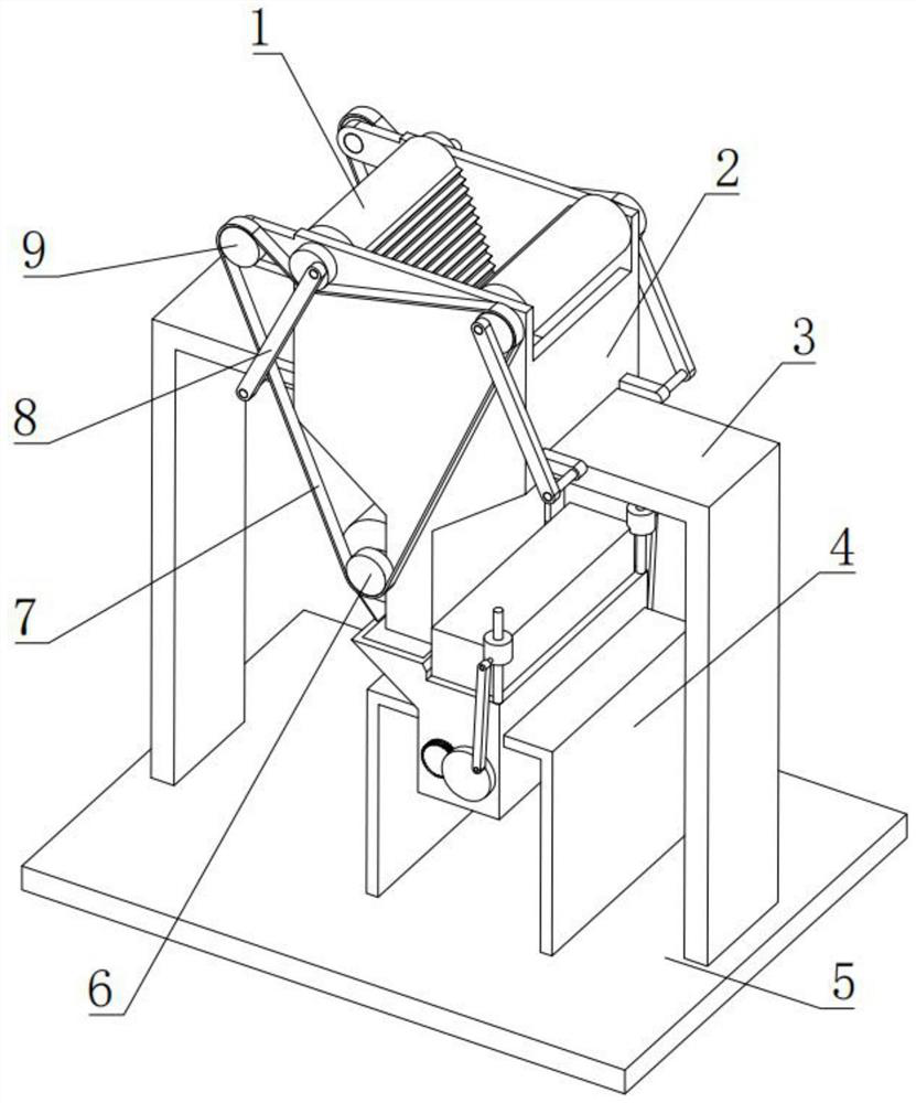
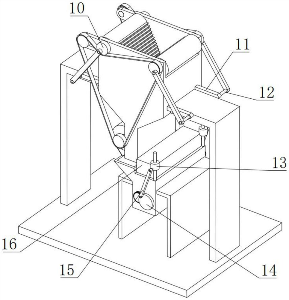
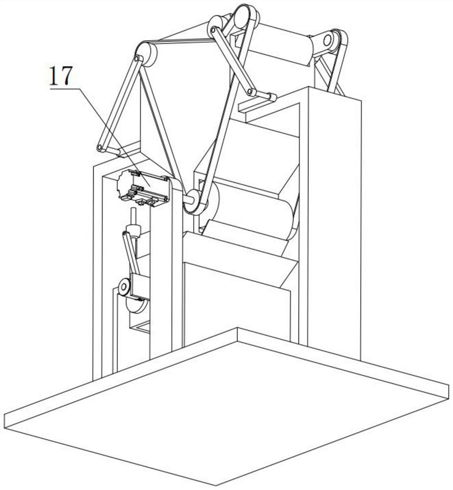
[0041] like Figure 1-Figure 16 As shown, the present invention includes a bottom plate 5, the upper side of the bottom plate 5 is fixedly connected to the lower end of the symmetrical L-shaped plate-3 vertical plate, and the upper end of the bottom plate 5 is fixedly connected to the lower side of the symmetrical L-shaped plate two-4 vertical plate, so The upper end of the bottom plate 5 is fixedly connected to the lower end of the vertical plate 24;

[0042] The opposite sides of the two L-shaped plates and the three horizontal plates are respectively fixedly connected to one side of the feeding box 2. The two long plates of the feeding box 2 are higher than the two short plates, and the two long plates of the feeding box ...


PUM


Abstract

The invention discloses a construction waste treatment equipment, comprising a bottom plate, which is characterized in that: the upper side of the bottom plate is fixedly connected to the lower end of a symmetrical L-shaped plate one vertical plate, and the upper end of the bottom plate is fixedly connected to the symmetrical L-shaped plate two On the lower side of the vertical plate, one end of the upper side of the bottom plate is fixedly connected to the lower end of the vertical plate, and the opposite sides of the two L-shaped plates and one horizontal plate are respectively fixed to one side of the feeding box, and the two long plates of the feeding box are higher than the two sides. The upper part of one side of the two long boards of the feeding box is respectively fixedly connected to one end of the corresponding support board. The invention relates to the field of construction waste treatment equipment, in particular to a construction waste treatment equipment. The device can realize that waste garbage is put into the device through the feeding box, and the garbage is crushed by two crushing plates. A set of cutting plates cuts the crushed garbage, and the crushed garbage passes through the feeding pipe Drop into the disposal box for crushing, so that the garbage crushing treatment is more thorough.

Description

technical field [0001] The invention relates to the field of garbage disposal equipment, in particular to a construction waste disposal equipment. Background technique [0002] With the development of my country's economy and the accelerated pace of urban and rural construction, some construction waste will inevitably be generated when demolishing buildings, such as cement, stones, nuts, screws, screws, gaskets, welding slag and welding rods accidentally abandoned during maintenance. Wait, most of them are mixed together. Some iron nails and short steel bars can be reused. They are mixed with construction waste. It is very difficult to sort out and it takes a long time. Generally, the staff will smash them together as construction waste and then recycle them. Doing it for other purposes not only increases the difficulty of crushing construction waste, but also wastes resources. Existing processing devices generally cannot recycle and reuse iron filings, which increases costs....

Claims


Application Information

Patent Timeline
Patent Type & Authority Patents(China)
IPC IPC(8): B02C1/04B02C23/10B08B1/02B02C23/00B65D90/58
CPCB02C1/043B02C23/10B08B1/005B08B1/02B02C23/00B65D90/587B02C2201/02B02C2201/06
Inventor 王喆
Owner 山东方泰建业有限公司
Why Eureka
Try Eureka