Electronic gear shifting handle mounting structure and assembling method

An installation structure, electronic shifting technology, applied in the direction of control device, transportation and packaging, vehicle parts, etc., can solve the problems of damage to electrical connectors, large installation force, easy damage or degradation of elastic parts, etc., to achieve convenient operation. Effect

Inactive Publication Date: 2020-12-18
VOYAH AUTOMOBILE TECH CO LTD
View PDF3 Cites 0 Cited by
  • Summary
  • Abstract
  • Description
  • Claims
  • Application Information

AI Technical Summary

Problems solved by technology

The disadvantage is that in order to ensure that the handle has sufficient pull-out force and a small fit clearance, the installation force of the handle is usually relatively large, and the assembly needs to use tools such as rubber hammers to install the handle in place. There is a high probability of damage to the electrical socket inside the handle during the assembly process. At the same time, after this installation method is disassembled and assembled several times, the matching structure and elastic parts are easily damaged or degraded

Method used


Image

  • Electronic gear shifting handle mounting structure and assembling method
  • Electronic gear shifting handle mounting structure and assembling method
  • Electronic gear shifting handle mounting structure and assembling method

Examples


Embodiment 1

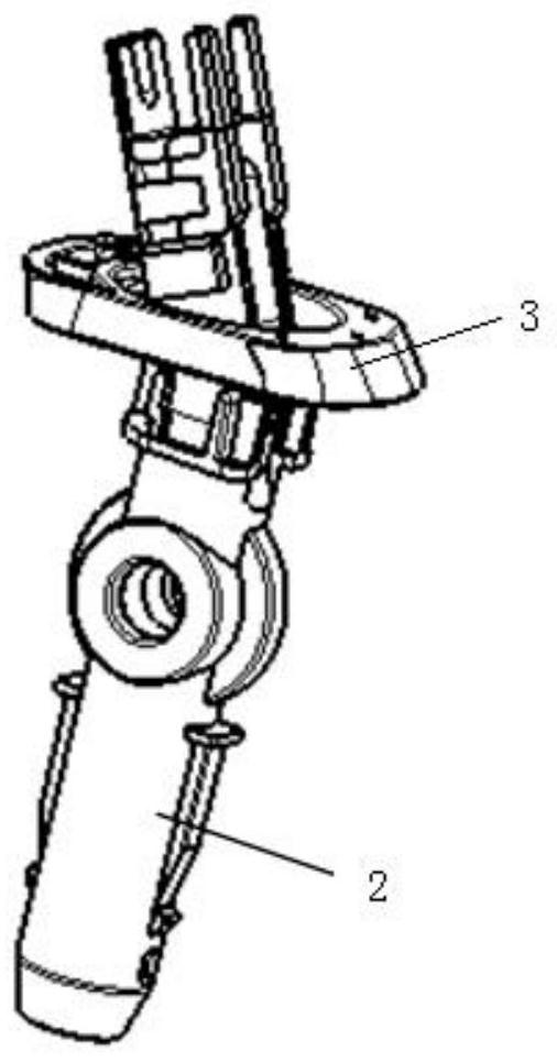
[0041] The matching form of the lock ring and the stop rod: according to Figure 7 The direction of view, after the assembly is completed, the relative position of the lock ring and the stop rod is as follows: Figure 7 In the state shown in the middle figure, the first limit rib 3-1 of the lock ring 3 is rotated to the bottom of the limit protrusion 2-1 of the stop rod 2 to ensure that the stop rod cannot move downward relative to the lock ring (i.e. the handle), which can ensure that the handle cannot be disengaged from the stop lever; Figure 7 The picture in the middle shows the state when the stopper rod 2 and the lock ring 3 are assembled. Relative to the middle picture, the lock rotates 30° counterclockwise around the axis of the stopper bar. At this time, the first limit rib 3-1 of the lock ring has been rotated to a proper position to ensure the limit There is no limit structure under the protrusion 2-1, and the stop rod 2 can be normally separated from the lock ring...

Embodiment 2

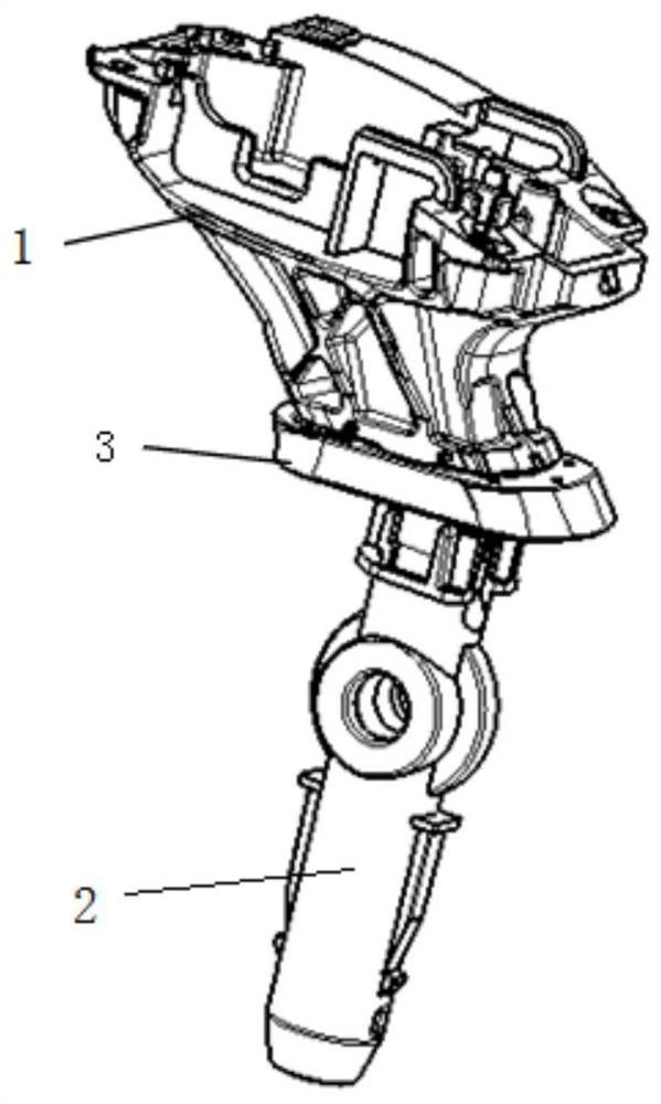
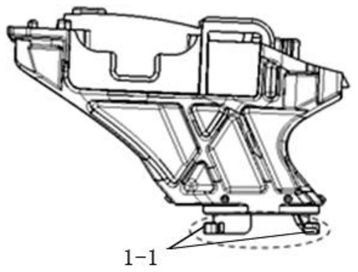
[0043] The matching form of the lock ring 3 and the handle skeleton 1: according to Figure 8 the view direction, Figure 8 , Figure 9 It is the state before assembly. At this time, the second limit rib 3-2 of the lock ring 3 is disengaged from the two limit bosses 1-1 of the handle frame 1, and the lock ring can be disengaged from the handle frame 1, but in order to lock before assembly The ring does not get loose from the handle skeleton, and a raised rib 1-2 ( Figure 9 shown); Figure 10 , Figure 11 For the state after the assembly is locked, according to Figure 9 In the direction of view, rotate 30° counterclockwise from the loosened state to the locked state. At this time, the second limit rib 3-2 of the lock ring 3 rotates to the top of the limit boss 1-1 of the handle frame to ensure that the handle frame 1 It cannot move relative to the lock ring 3 in the axial direction, and at the same time, the raised rib 1-2 on the handle frame 1 just rotates into the limi...

Embodiment 3

[0045] The overall cooperation form of the lock ring, the retaining rod and the handle frame: in combination with Embodiment 1 and Example 2, the position of the lock ring rotation ensures that the second limit rib 3-2 is on the upper part of the limit boss 1-1 of the handle frame. Simultaneously the first limiting rib 3-1 is at the bottom of the limiting projection 2-1 (the limiting projection 2-1 of the retaining bar and the limiting boss 1-1 of the handle skeleton are arranged according to the rotation of 90°), at this time Connect the handle frame with the stop rod as a whole through the lock ring, such as Figure 13As shown; 30°clockwise rotation is the loosened state. At this time, the second limiting rib 3-2 of the lock ring avoids the limiting boss 1-1, and the first limiting rib 3-1 avoids the protrusion of the stop rod at the same time. Block 2-1, the blocking rod can be separated from the handle frame (the lock ring will not fall off from the handle frame due to the...


PUM


Abstract

The invention discloses an electronic gear shifting handle mounting structure and an assembling method. The electronic gear shifting handle mounting structure comprises a handle framework, a stop lever and a lock ring; the handle framework is in limiting connection with the lock ring from the upper portion, the stop lever is in limiting connection with the lock ring from the lower portion, the upper portion of the stop lever is fixed into the handle framework, and a plurality of first limiting ribs used for limiting the stop lever and a plurality of second limiting ribs used for limiting the handle framework are arranged on an inner circle of the lock ring. According to the electronic gear shifting handle mounting structure and the assembling method, fasteners are not needed for auxiliaryfixing; and a handle electric appliance plug connector is protected, and the pull-out force is hardly influenced after the handle electric appliance plug connector is disassembled and assembled for many times.

Description

technical field [0001] The invention belongs to the technical field of automobile chassis, and in particular relates to an installation structure and an assembly method of an electronic shift handle. Background technique [0002] The common installation methods of the electronic shift handle are fastened by screws and quick-inserted through elastic parts. [0003] The screw tightening installation method has the advantage that there is no gap between the shift handle and the shift lever through screw locking, and the installation force of the handle to the shift lever is usually small. The disadvantage is that the assembly is cumbersome and takes a long time. It needs to be equipped with a special tool gun for tightening screws. The assembly cost is high and the handle style is limited. If the handle is assembled on the OEM assembly line), if the electronic shift handle is supplied integrally with the mechanism, then the opening of the auxiliary instrument is required to be...

Claims


Application Information

Patent Timeline
Patent Type & Authority Applications(China)
IPC IPC(8): B60K20/02
CPCB60K20/02
Inventor 张雷博陈子轩
Owner VOYAH AUTOMOBILE TECH CO LTD
Why Eureka
Try Eureka