Aluminum foil winding device having adjustable tightness
A winding device and aluminum foil technology, which is applied in the direction of winding strips, transportation and packaging, thin material processing, etc., can solve the problems of poor practicability, adjustment of aluminum foil winding tightness, troublesome operation, etc.
- Summary
- Abstract
- Description
- Claims
- Application Information
AI Technical Summary
Problems solved by technology
Method used
Image
Examples
Embodiment 1
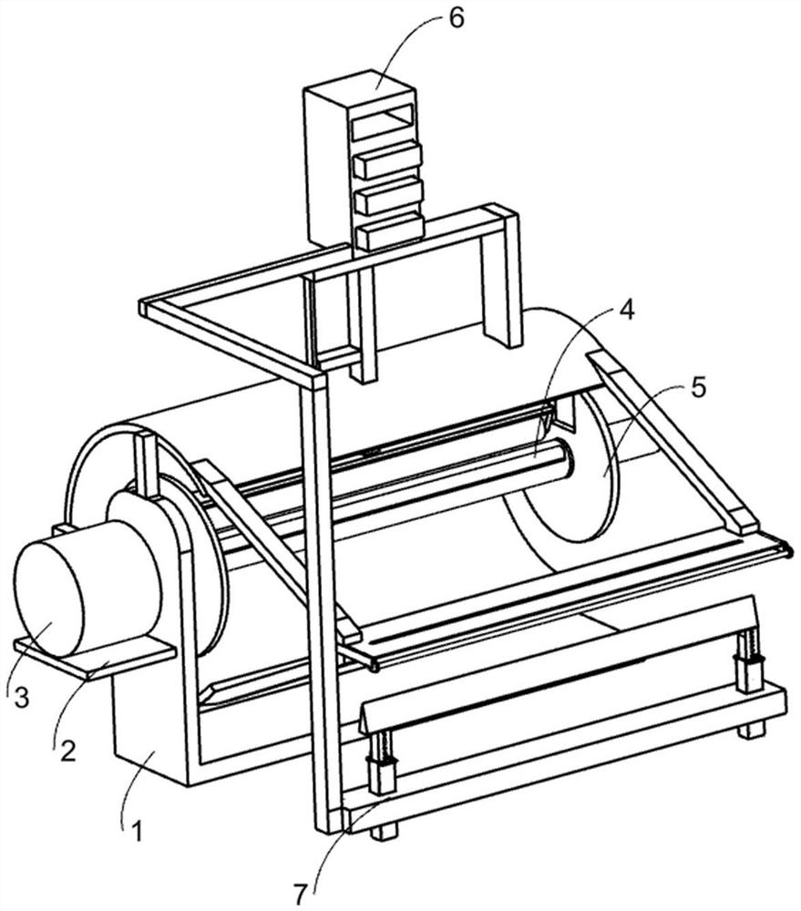
[0022] An aluminum foil winding device with adjustable tightening degree, such as Figure 1-7 As shown, it includes a base 1, a supporting plate 2, a motor 3, a clamping mechanism 4, an adjusting mechanism 5 and a tightening mechanism 6. The supporting plate 2 is fixed on one side of the base 1, and the motor 3 is fixed on the On the upper side of the pallet 2 , the clamping mechanism 4 for clamping the reel is set on the base 1 , and the adjusting mechanism 5 and the tightening mechanism 6 are both set on the clamping mechanism 4 .
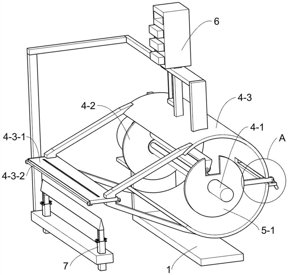
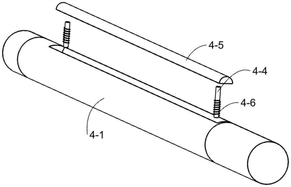
[0023] Further, the clamping mechanism 4 includes a power shaft 4-1, a fixed disk 4-2, an annular frame 4-3, a ferrule 4-3-1, a movable rod 4-3-2, a telescopic rod 4-4, The clamping rod 4-5 and the compression spring 4-6, the power shaft 4-1 is arranged on the base 1 through a bearing and fixedly connected with the output shaft of the motor 3, and the fixed disk 4-2 is fixed on the power shaft 4 -1 and close to the base 1, the ring frame 4-3 is ...
Embodiment 2
[0029] On the basis of Example 1, such as Figure 1-2 As shown in and 5-6, the tightening mechanism 6 for adjusting the tightness of aluminum foil winding is set on the ring frame 4-3, and the tightening mechanism 6 includes a fixed seat 6-1, a lifting rod 6-2, Lifting frame 6-3, movable wheel 6-4, pressure box 6-5, gravity block 6-6 and scale 6-7, described fixed seat 6-1 is fixedly arranged on the upper side of annular frame 4-3, so One end of the fixed seat 6-1 is provided with a sliding hole and the lifting rod 6-2 is slidably arranged in the sliding hole, the lifting rod 6-2 passes through the top of the ring frame 4-3, and the lifting frame 6-3 Fixedly located at the lower end of the elevating rod 6-2 and located in the ring frame 4-3, the movable wheel 6-4 is rotatably arranged on the elevating frame 6-3 and the movable wheel 6-4 can enter the moving plate 5-1 In the arc-shaped groove on the top, the movable wheel 6-4 is used to compress the aluminum foil during the wi...
Embodiment 3
[0032] On the basis of Example 2, such as Figure 1-2 and Figure 6-7 As shown, it also includes a shearing mechanism 7 for cutting the aluminum foil. The shearing mechanism 7 is arranged on the pressure box 6-5. The shearing mechanism 7 includes a connecting rod 7-1, a horizontal plate 7-2, Fixed frame 7-3, cutter 7-4, fixed block 7-5, toggle lever 7-6, clamping ball 7-7 and telescopic spring 7-8, described connecting rod 7-1 is fixedly arranged on pressure box 6 -5 on one side, the horizontal plate 7-2 is fixed on the lower end of the connecting rod 7-1 and is located below the ferrule 4-3-1, and the horizontal plate 7-2 is fixed with two symmetrical fixed Frame 7-3, the cutter 7-4 for cutting the aluminum foil is slidably arranged in the fixed frame 7-3 and eight slots are opened on both sides of the cutter 7-4, the fixed One end of the frame 7-3 away from the horizontal plate 7-2 is fixedly provided with two symmetrical fixed blocks 7-5 and a slide hole is provided on th...
PUM
 Abstract
Description
Claims
Application Information
 - R&D
- Intellectual Property
- Life Sciences
- Materials
- Tech Scout
- Unparalleled Data Quality
- Higher Quality Content
- 60% Fewer Hallucinations
Browse by: Latest US Patents, China's latest patents, Technical Efficacy Thesaurus, Application Domain, Technology Topic, Popular Technical Reports.
© 2025 PatSnap. All rights reserved.Legal|Privacy policy|Modern Slavery Act Transparency Statement|Sitemap|About US| Contact US: help@patsnap.com


