
Anti-oil-dripping liquid loading and unloading platform device

A loading and unloading platform, anti-drip technology, applied in liquid distribution, transportation or transfer devices, distribution devices, special distribution devices, etc., can solve the problems of harming the health of on-site workers, pollution, and waste of oil products on-site environment.

Active Publication Date: 2020-12-18
郑州智慧通测控技术有限公司
View PDF9 Cites 1 Cited by
  • Summary
  • Abstract
  • Description
  • Claims
  • Application Information

AI Technical Summary

Problems solved by technology

[0002] The crane tube is an important equipment for liquid loading and unloading in the petrochemical industry. When the crane tube is filled with liquid, it needs to be aligned with the tank mouth of the tanker. The traditional way of moving the crane tube is to use manual dragging to drag the crane tube to the tank mouth. Right above, after which the crane tube descends and starts to fill the liquid; currently there is an automatic loading crane tube that can be manually controlled, and the on-site personnel visually align the crane tube with the tank mouth, and then manually control the movement of the crane tube through the control cabinet, but due to this Alignment depends on the vision of the on-site personnel. Since the observation angle of the on-site personnel is mostly on the side of the crane tube, multiple cameras or multiple on-site personnel are usually required to provide different angles of view to achieve the purpose of correction. However, this will be more video equipment or on-site personnel involved, and the on-site oil and gas volatilization will also endanger the health of on-site staff; Therefore, the vertical pipe after being pulled out will drop oil droplets downward, resulting in waste of oil products and environmental pollution on site

Method used


Image

  • Anti-oil-dripping liquid loading and unloading platform device
  • Anti-oil-dripping liquid loading and unloading platform device
  • Anti-oil-dripping liquid loading and unloading platform device

Examples


Embodiment Construction

[0031] The following will clearly and completely describe the technical solutions in the embodiments of the present invention with reference to the accompanying drawings in the embodiments of the present invention. Obviously, the described embodiments are only some, not all, embodiments of the present invention. Based on the embodiments of the present invention, all other embodiments obtained by persons of ordinary skill in the art without making creative efforts belong to the protection scope of the present invention.

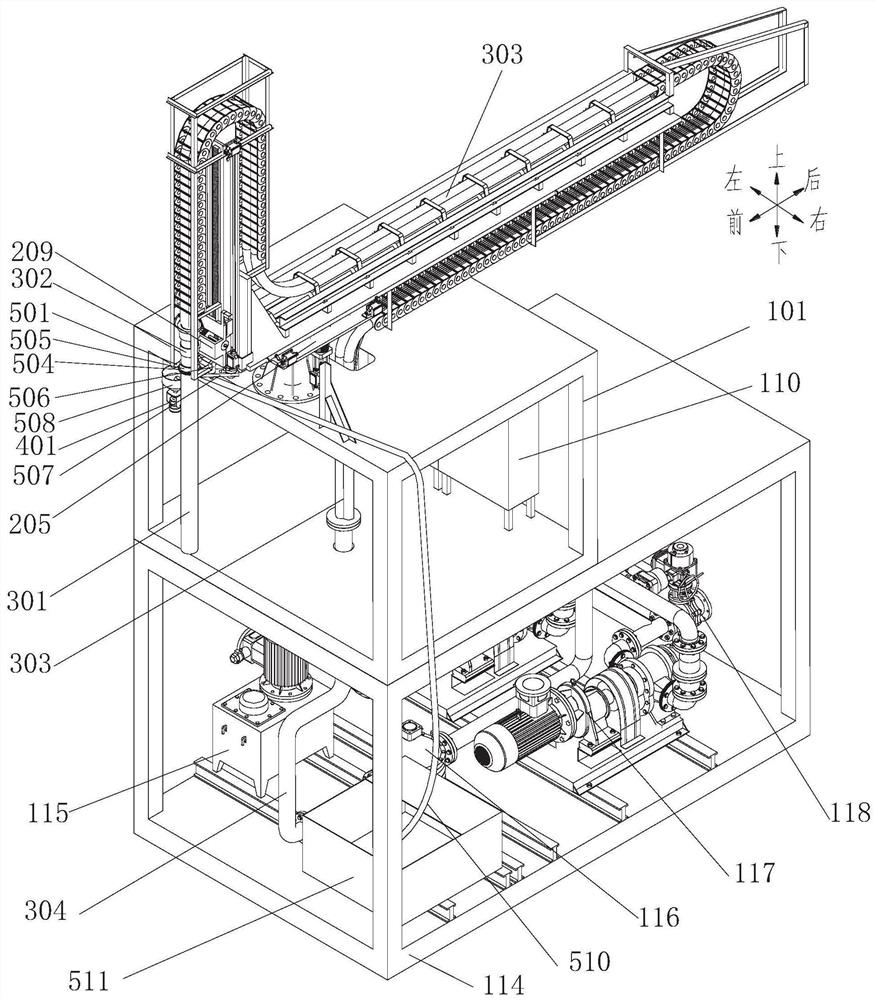
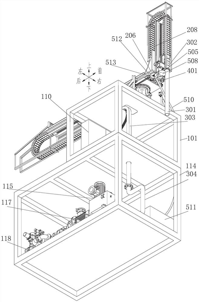
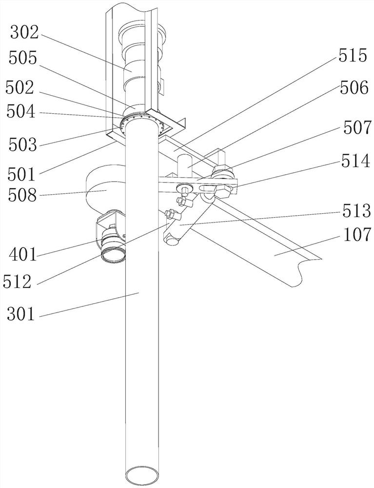
[0032] Such as Figure 1 to Figure 6 As shown, an anti-drip oil liquid loading and unloading platform device includes a pump skid, an upper bracket 101 arranged on the upper end surface of the pump skid, a remote alignment system, an automatic loading crane pipe installed on the upper bracket 101, and a control box 110 and scraper assembly;

[0033]The pump skid includes a lower bracket 114, a hydraulic pump station 115 arranged in the lower bracket 114, a re...


PUM


Abstract

The invention relates to an anti-oil-dripping liquid loading and unloading platform device which comprises a pump skid-mounted device, an upper support arranged on the upper end face of the pump skid-mounted device, a remote alignment system, an automatic loading crane pipe installed on the upper support, a control box and an oil scraping assembly. The pump skid-mounted device comprises a lower support, a hydraulic pump station arranged in the lower support, a recycling container, an oil receiving opening, an oil pump and a flow meter, wherein the oil receiving opening, the oil pump and the flow meter are sequentially connected through a pipeline in the flow direction of fluid, and an outlet of the flow meter is connected with an oil conveying pipe. Movement and lifting of a vertical pipeare remotely controlled based on a real-time transmission image of a first camera so that the vertical pipe can be quickly aligned with a tank opening of a tank truck, oil on the pulled-out vertical pipe is received by an oil receiving bowl and recycled into the recycling container, accordingly, on-site environment maintenance personnel are not needed, on-site unattended operation is realized, andthe labor cost is reduced. The anti-oil-dripping liquid loading and unloading platform device can be transferred to other stations for reuse, and the enterprise cost is saved.

Description

technical field [0001] The invention belongs to the technical field of crane tube loading, and in particular relates to an anti-dripping oil liquid loading and unloading platform device. Background technique [0002] The crane tube is an important equipment for liquid loading and unloading in the petrochemical industry. When the crane tube is filled with liquid, it needs to be aligned with the tank mouth of the tanker. The traditional way of moving the crane tube is to use manual dragging to drag the crane tube to the tank mouth. Right above, after which the crane tube descends and starts to fill the liquid; currently there is an automatic loading crane tube that can be manually controlled, and the on-site personnel visually align the crane tube with the tank mouth, and then manually control the movement of the crane tube through the control cabinet, but due to this Alignment depends on the vision of the on-site personnel. Since the observation angle of the on-site personnel...

Claims


Application Information

Patent Timeline
Patent Type & Authority Applications(China)
IPC IPC(8): B67D7/42B67D7/54
CPCB67D7/42B67D7/54
Inventor 王仁甫郜俊红穆怀浩訾东风高启铭狄蒙
Owner 郑州智慧通测控技术有限公司
Learn More