Swing check valve

A check valve, swing type technology, applied in the direction of lift valve, valve detail, control valve, etc., can solve the problems of large impact force on the sealing surface of the valve seat, fast closing speed, valve damage, etc., to achieve reliable closing and sealing, The effect of slow closing speed and low manufacturing cost

Active Publication Date: 2020-12-18
浙江冠正阀门股份有限公司
View PDF2 Cites 0 Cited by
  • Summary
  • Abstract
  • Description
  • Claims
  • Application Information

AI Technical Summary

Problems solved by technology

Its disadvantages are: in the process of rotating and closing the check valve disc around the pin shaft, the closing speed is prone to be too fast, resulting in excessive impact force on the sealing surface of the valve disc and the s

Method used


Image

  • Swing check valve
  • Swing check valve
  • Swing check valve

Examples


Embodiment Construction

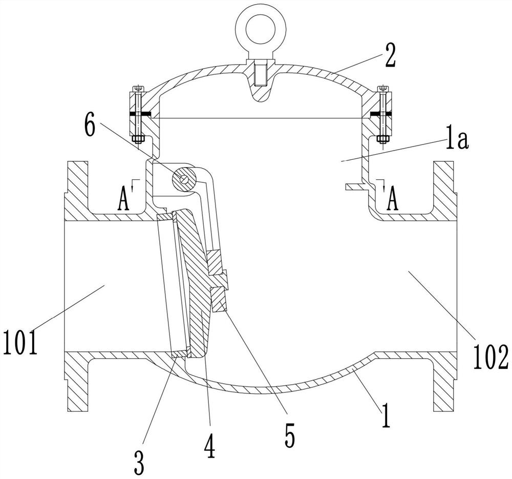
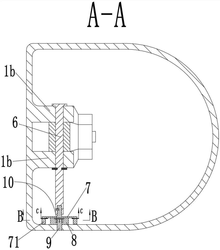
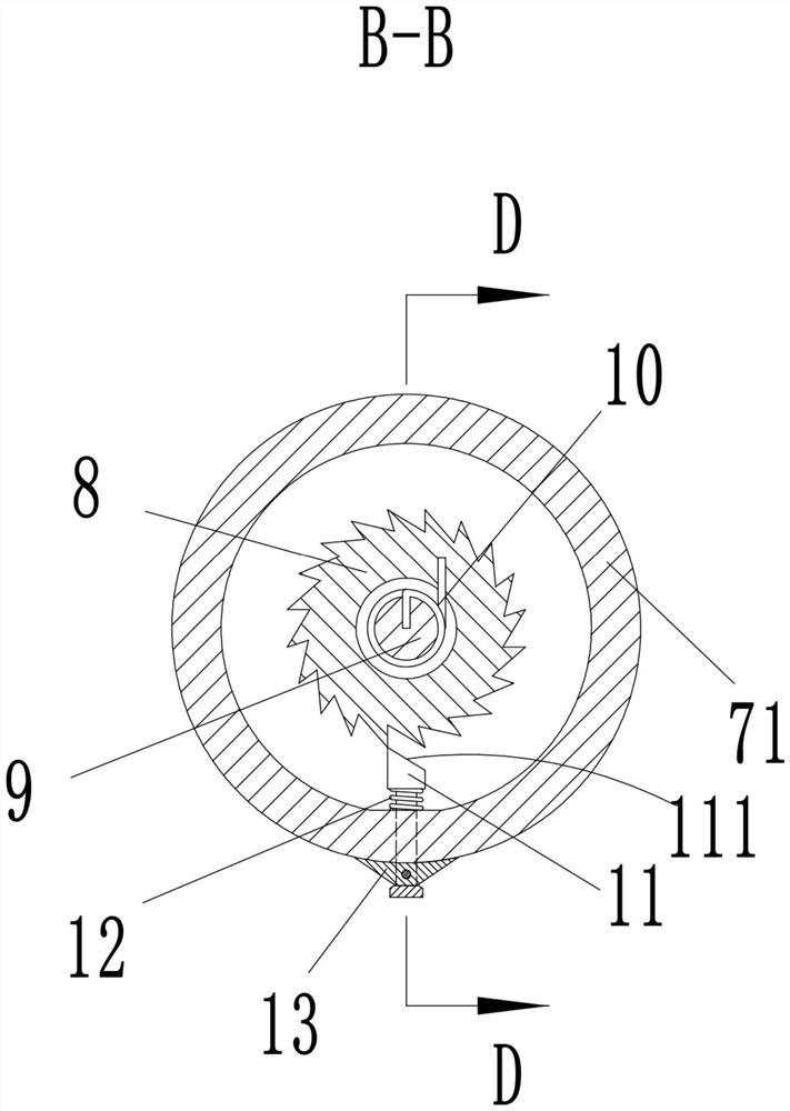
[0022] see Figure 1-6 As shown, a swing check valve includes a valve body 1, the valve body 1 is provided with a valve chamber 1a, and the side of the valve body 1 is provided with an inlet pipe 101 and an outlet pipe communicated with the valve chamber 1a 102; the valve cover 2 is fixedly installed at the opening of the upper end of the valve chamber 1a, and the inner wall of the valve chamber 1a is rotatably connected with the shaft 6 perpendicular to the inlet pipe 101 above the inlet pipe 101, on the shaft 6 A rocker 5 is fixedly installed, and the valve plate 4 for controlling the opening and closing of the inlet pipe 101 is fixedly installed on the end of the rocker 5 away from the shaft 6; a turntable 7 is fixedly installed on one end of the shaft 6, and the turntable 7. An annular flange 71 is provided on the end face away from the shaft 6. A protruding shaft 9 coaxial with the shaft 6 is fixedly installed on the inner side of the valve cavity 1a. The protruding shaft...


PUM


Abstract

The invention discloses a swing check valve. The swing check valve comprises a valve body. A valve cavity is formed in the valve body. An inlet pipe and an outlet pipe are arranged on the side face ofthe valve body. A valve cover is fixedly installed at an opening in the upper end of the valve cavity. The valve is characterized in that a shaft rod is rotatably connected to the inner side wall ofthe valve cavity, a rocker is fixedly installed on the shaft rod, and a valve plate is fixedly installed on the rocker. A rotary disc is fixedly installed at one end of the shaft rod. An annular convex edge is arranged on the end face, away from the shaft rod, of the rotary disc. A convex shaft coaxial with the shaft rod is fixedly installed on the inner side of the valve cavity. A ratchet wheel located in the annular convex edge is arranged on the convex shaft. An arc-shaped annular groove is formed in the outer side of the circumference of the convex shaft. A protruding block extending intothe arc-shaped annular groove is arranged at the side wall of an inner hole of the ratchet wheel. A torsional spring used for forcing the ratchet wheel to drive the protruding block to be pressed at one end of the arc-shaped annular groove is arranged between the convex shaft and the ratchet wheel. A locking block assembly is arranged in the rotary disc. The swing check valve not only is simple instructure, but also can be used for automatically filling a pump.

Description

technical field [0001] The invention belongs to the technical field of pipeline valves, in particular to a swing check valve. Background technique [0002] The check valve is a commonly used valve in the pipeline system, which is mainly installed at the outlet of the pump, and it is used to connect and check the fluid medium in the pipeline system. The existing swing check valve mainly includes a valve body, a valve seat and a check disc. The pin shaft is installed in the inner cavity of the valve. When the medium enters the inner cavity of the valve from the inlet side of the valve, the medium pushes the check valve disc to rotate around the pin shaft to open. When no medium enters the valve inlet side, the check valve disc rotates around the pin shaft. closure. Its disadvantages are: in the process of rotating and closing the check valve disc around the pin shaft, the closing speed is prone to be too fast, resulting in excessive impact force on the sealing surface of the...

Claims


Application Information

Patent Timeline
IPC IPC(8): F16K15/03F16K47/02F16K1/20F16K1/32
CPCF16K15/033F16K47/023F16K1/20F16K1/32
Inventor 段井胜刘秋燕
Owner 浙江冠正阀门股份有限公司
Why Eureka
Try Eureka