Blockchain transaction terminal with forcible entry self-destruction function
A transaction terminal and blockchain technology, applied in the field of blockchain transaction terminals, can solve the problems of general portability of the transaction terminal body, soreness of finger joints, and high physical energy consumption of users, so as to be conducive to popularization and use and not easy to soreness. , the effect of reducing physical consumption
- Summary
- Abstract
- Description
- Claims
- Application Information
AI Technical Summary
Problems solved by technology
Method used
Image
Examples
Embodiment 1
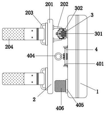
[0033] A block chain transaction terminal with demolition and self-destruction, including a transaction terminal main body 1, a portable mechanism 2 is provided on the left side of the transaction terminal main body 1, and the convenient mechanism 2 includes an arc-shaped plate 201, a support plate 202, a groove ring 203 and The elastic ring 204 and the arc plate 201 are located on the left side of the transaction terminal main body 1, and the upper right surface of the arc plate 201 is sequentially provided with two support plates 202 from bottom to top, and the left end of the support plate 202 is aligned with the arc. The contact surface of the plate 201 is fixedly connected, the support plate 202 is connected with the transaction terminal main body 1, and the four corners of the left surface of the arc plate 201 are provided with groove rings 203, and the groove ring 203 is fixedly connected with the contact surface of the arc plate 201. An elastic ring 204 is arranged betw...
Embodiment 2
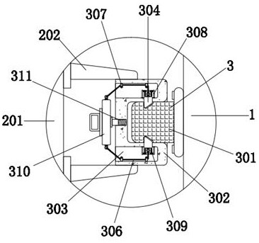
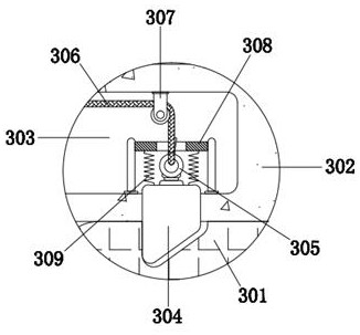
[0035] As an option, see figure 1 , 2, 3 and 5, a block chain transaction terminal with demolition and self-destruction, the transaction terminal main body 1 is connected with the arc plate 201 through the docking mechanism 3, and the docking mechanism 3 includes a plug-in block 301, a slot 302, a groove 303, a card Block 304, ring 305, stay cord 306, fixed pulley 307, concave plate 308, compression spring 309, pull block 310 and tension spring 311, insert block 301 is positioned at the left surface top of transaction terminal main body 1, insert block 301 and transaction The contact surface of the terminal body 1 is fixedly connected, the outer side of the insert block 301 is sleeved with a slot 302, the inner wall of the slot 302 fits with the contact surface of the insert block 301 with a gap, and the upper and lower ends of the left surface of the slot 302 are provided with grooves 303, a block 304 is inserted inside the inner bottom of the groove 303, and the block 304 p...
Embodiment 3
[0038] As an option, see figure 1 and 4 , a block chain transaction terminal with demolition and self-destruction, the left surface of the transaction terminal main body 1 is provided with an anti-off mechanism 4, and the anti-off mechanism 4 includes a sliding rod 401, a sleeve 402, a bump 403, a collar 404, and a sticker 405 and an elastic band 406, the slide bar 401 is located on the left side of the transaction terminal main body 1, the upper and lower ends of the right side of the slide bar 401 are fixedly connected with the contact surface of the transaction terminal main body 1, and the outer wall of the slide bar 401 is sleeved with a sleeve 402. The inner wall of the cylinder 402 is matched with the outer wall of the slide rod 401 with a gap. The left side of the outer wall of the sleeve 402 is provided with a protrusion 403, which is connected to the sleeve 402 through a ball bearing. The left side of the protrusion 403 is provided with a collar 404. , the collar 40...
PUM
 Abstract
Description
Claims
Application Information
 - R&D
- Intellectual Property
- Life Sciences
- Materials
- Tech Scout
- Unparalleled Data Quality
- Higher Quality Content
- 60% Fewer Hallucinations
Browse by: Latest US Patents, China's latest patents, Technical Efficacy Thesaurus, Application Domain, Technology Topic, Popular Technical Reports.
© 2025 PatSnap. All rights reserved.Legal|Privacy policy|Modern Slavery Act Transparency Statement|Sitemap|About US| Contact US: help@patsnap.com


