Combined antenna

A technology of combining antennas and sending pots, applied in the directions of antennas, antenna coupling, and antenna parts, etc., can solve the problems of large floor space, rollover or inversion, frequent adjustment, etc. , the effect of strengthening the antenna

Inactive Publication Date: 2020-12-18
吴美珠
View PDF12 Cites 0 Cited by
  • Summary
  • Abstract
  • Description
  • Claims
  • Application Information

AI Technical Summary

Problems solved by technology

[0004] The main purpose of the present invention is to overcome the deficiencies of the prior art and provide a combined antenna to solve the problem that the antenna is easily disturbed by sea waves and tidal waves when it is working, and the antenna will rotate, or even roll over or be inverted. The transmitting and receiving structure of the antenna is installed in a distributed manner, and the degree of interference is small, but the installation distance is long and the area is large. In order to improve the magnetic induction, frequent adjustments are required, which is time-consuming and labor-intensive.

Method used


Image

  • Combined antenna
  • Combined antenna
  • Combined antenna

Examples


Embodiment 1

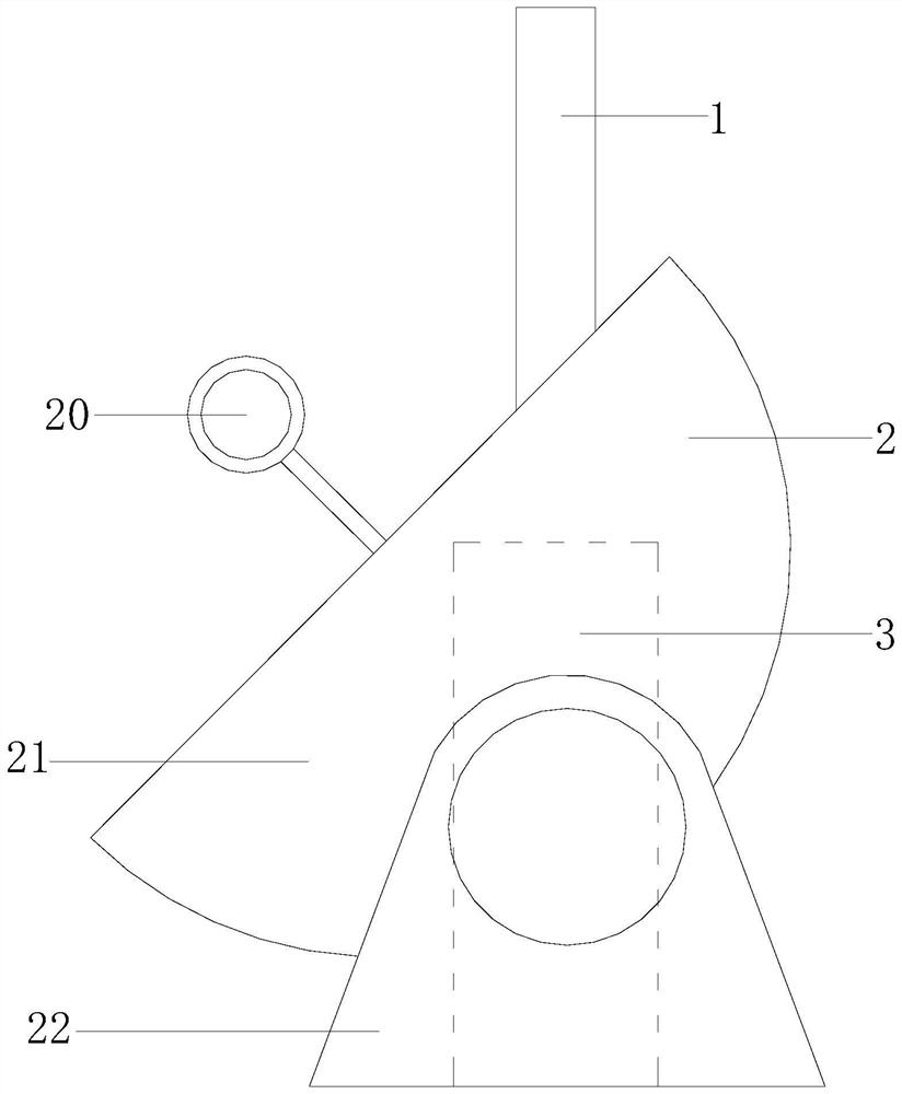
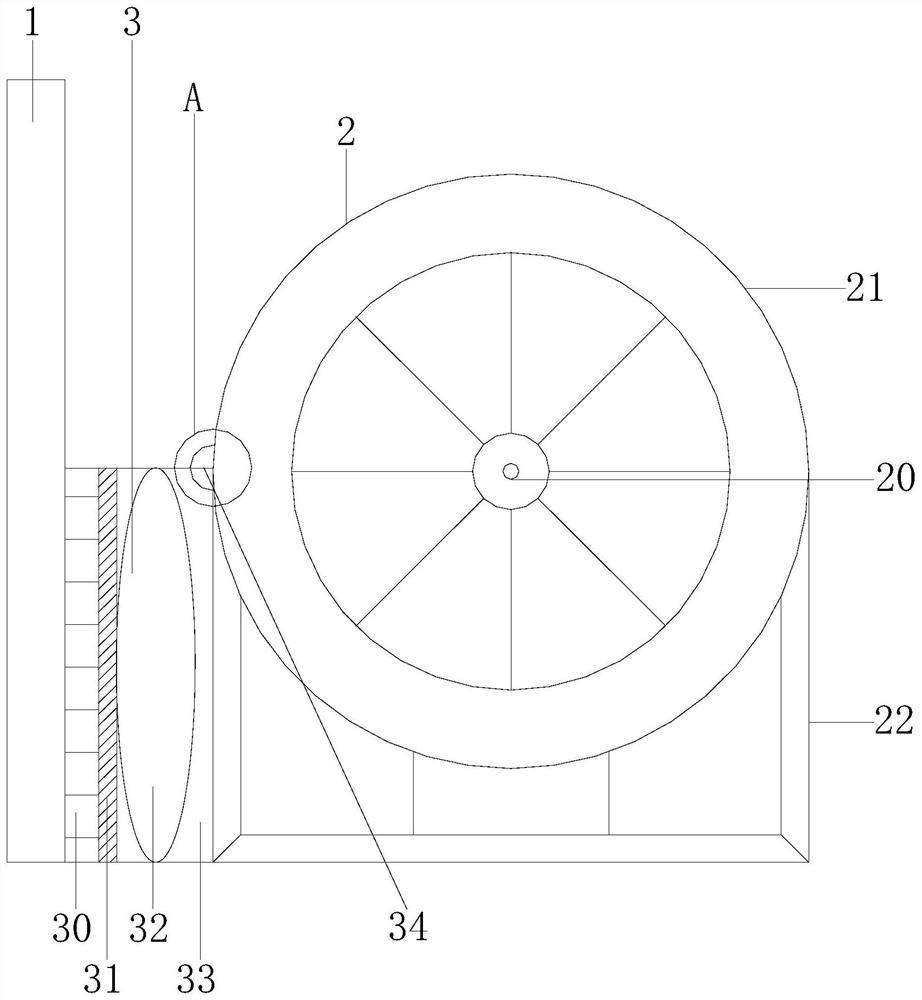
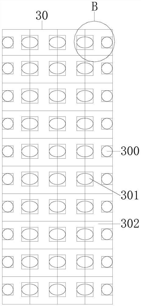
[0022] Example 1 see Figure 1-4 , the present invention provides a combined antenna technical solution: its structure includes a signal receiving rod 1, a signal sending pot 2, and a magnetic control box 3, the signal receiving rod 1 is connected to the signal sending pot 2 and the magnetic control box 3, and the The signal receiving rod 1 is used for signal reception, the signal sending pot 2 is used for signal sending, and the magnetic control box 3 is used for controlling magnetic waves and stabilizing the signal receiving rod 1 and the magnetic control box 3. The signal sending pot 2 is composed of a sending pot line 20, The sending pot body 21 and the pot frame 22 are composed, the sending pot line 20 is installed on the sending pot body 21, the sending pot body 21 is connected with the pot frame 22, the magnetic control box 3 includes a cladding structure 30, a partition Plate structure 31, balance structure 32, magnetic control box frame 33, and pot holder 34. The part...

Embodiment 2

[0024] Example 2 see Figure 5 , 6 , the present invention provides a combined antenna technical solution: the structure of the balance structure 32 includes a vertical ring 320, a falling ball 321, a horizontal ring 322, and a balance frame 323, and the vertical ring 320, the horizontal ring 322 and the falling ball 321 are installed on On the balance frame 323, the vertical ring 320 and the horizontal ring 322 form a vertical structure, the vertical ring 320 is equipped with a vertical ring movable ball 3200, the vertical ring 320 is connected with a vertical ring shaft device 3201, and the falling ball 321 Dropping ball buckle plate 3210 is installed, and described horizontal ring 322 is equipped with horizontal ring movable ball 3220, and described horizontal ring 322 is connected with horizontal ring axle device 3221, and described pot holder 34 comprises horizontal rail 340, movable card wheel 341, Clamping shaft 342, friction coating 343, the pot holder 34 plays the ro...


PUM


Abstract

The invention discloses a combined antenna, which structurally comprises a signal receiving rod, a signal sending pot and a magnetic control box, the signal receiving rod and the signal sending pot are connected with the magnetic control box, the signal sending pot is composed of a sending pot line, a sending pot body and a pot frame; the sending pot line is installed on the sending pot body, andthe sending pot body is connected with a pot frame shaft. The magnetic control box comprises a wrapping structure, a partition plate structure, a balance structure, a magnetic control box frame and apot fixing device, wherein the wrapping structure is connected with the partition plate structure through a rail, the balance structure is installed on the magnetic control box frame, the magnetic control box frame is provided with the pot fixing device, and the wrapping structure comprises a buckle device, a stretcher and a wrapping joint plate. According to the invention, the magnetic control box plays a role in resisting magnetic wave interference and reinforcing the antenna, the installation occupied area of the antenna is reduced through compact installation, the independent signal receiving and transmitting effect is good, and the balance structure plays a role in isolating interference magnetic waves.

Description

technical field [0001] The invention relates to the field of antennas, in particular to a combined antenna. Background technique [0002] The antenna is a kind of converter, which converts the guided wave propagating on the transmission line into electromagnetic waves propagating in the unbounded medium. The buoy communication technology is developed on the basis of traditional wireless communication technology and is generally placed on the sea level . [0003] The antennas in the prior art are easily disturbed by sea waves and tidal waves when they are working, and the antennas will rotate, or even roll over or be inverted. The transmitting and receiving structures of the antennas are distributed and installed in a combined manner, which has a small degree of interference but takes up a long installation distance. The area is large, and frequent adjustments are required to improve the magnetic induction, which is time-consuming and laborious. Contents of the invention ...

Claims


Application Information

Patent Timeline
Patent Type & Authority Applications(China)
IPC IPC(8): H01Q1/52H01Q1/12H01Q1/34H01Q19/12H01Q21/28
CPCH01Q1/12H01Q1/34H01Q1/525H01Q1/526H01Q19/12H01Q21/28
Inventor 吴美珠
Owner 吴美珠
Why Eureka
Try Eureka