Compact efficient vacuum boiler

A vacuum boiler, compact technology, applied in the direction of steam boiler, steam boiler accessories, steam boiler components, etc., can solve the problems of steam loss of scouring ability, affecting boiler heat exchange efficiency, weak heat exchange capacity, etc. The effect of reducing the floor area and space, reducing the amount of heat exchange, and reducing the workload

Active Publication Date: 2018-01-09
ANYANG FANGKUAI BOILER
View PDF7 Cites 0 Cited by
  • Summary
  • Abstract
  • Description
  • Claims
  • Application Information

AI Technical Summary

Problems solved by technology

[0002] The three-pass vacuum boiler is widely used in industrial and civil fields as a heat exchange equipment. The common structure of this equipment is to weld the tube plates at the front and back of the furnace, connect the smoke pipes to the front and rear tube plates, and set the front and rear of the furnace. The front smoke box and the rear smoke box, the front smoke box and the rear smoke box are also called the rotary chamber. The smoke after combustion enters the rear smoke box through the furnace, and passes through the smoke pipe from the rear smoke box to the front smoke box room to complete the second return journey. Heat exchange, and then continue to flow backward from the front smoke box through the smoke pipe to complete the heat exchange of the third return pass. At present, this commonly used traditional boiler structure has the following defects: First, the boiler must be long enough, because the smoke pipe and the furnace are two Both ends are fixed and welded on the tube plate. In the length direction of the smoke tube, the smoke tube has restraint stress on the furnace. When heating, the flame passes through the furnace and then transfers to the smoke tube area; The gallbladder expands more and the smoke pipe expands less, so the smoke pipe will form constraints on both ends of the furnace gall when heating. In order to reduce the damage to the boiler caused by this effect, the smoke pipe must be long enough to reduce the impact. This structure makes the boiler The lower limit of the length of the boiler is limited; the second is that the flue gas in the tube bundle of this boiler first reaches the rear smoke box during heat exchange, and then enters the tube bundle. In order to reduce the energy loss from the rear smoke box to the tube bundle, the rear smoke box generally needs to be enough length, generally about 500mm, which also limits the lower limit of the length of the boiler. After coming out of the tube bundle, it will be collected into the front smoke box, and then redistributed to the next return tube bundle. The cross section leads to the redistribution of the vortex area and velocity, and the pulsating velocity perpendicular to the flow direction leads to increased resistance, so this process is accompanied by a large resistance loss; the third is that this kind of product is labor-intensive and time-consuming in production. When making the return boiler, it is necessary to weld the front and rear smoke boxes to the tube plate first, and then weld the smoke tubes. The welding of the smoke boxes and the smoke tubes cannot be carried out at the same time. The process must be connected in series, and the welding workload is large; The current three-pass vacuum boiler generally has two layers of heat exchange tube bundles inside the furnace body. Each layer of tube bundles consists of two groups of left and right. The steam rises and completes heat exchange with the heat exchange tube bundles; after the heat exchange is completed, it becomes condensed water along the channel wall. When the condensate flows down, when the condensed water accumulates more and more, the liquid droplets drip on the outer wall of the lower heat exchange tube, forming a water film, which seriously affects the heat exchange effect, and the effect becomes more obvious as the steam and condensed water droplets are on the same Heat exchange occurs when a section passes and meets, and mass exchange occurs, that is, it becomes low-quality wet steam
Even if it can continue to rise, the heat transfer capacity is weak. The smaller the product cross-section, that is, the steam liquid level, the more obvious the impact, until the deterioration makes the steam lose its flushing ability, which seriously affects the heat transfer efficiency of the boiler. Therefore, the current three-pass vacuum boiler field needs a A compact and efficient technical solution

Method used


Image

  • Compact efficient vacuum boiler
  • Compact efficient vacuum boiler
  • Compact efficient vacuum boiler

Examples


Embodiment Construction

[0015] In order to more fully explain the implementation of the present invention, implementation examples of the present invention are provided. These implementation examples are only illustrations of the present invention, and do not limit the scope of the present invention.

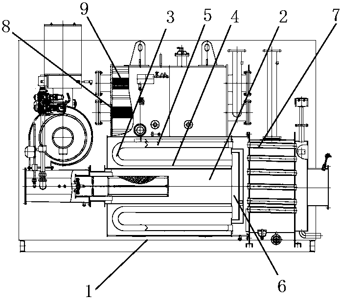
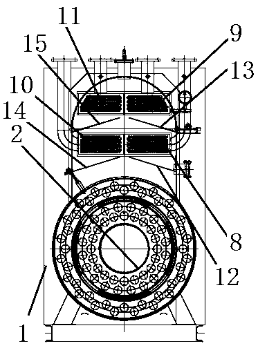
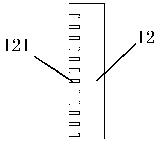
[0016] A further detailed explanation of the present invention is given in conjunction with the accompanying drawings. In the accompanying drawings, each label is: 1: Furnace body; 2: Furnace gall; 3: U-shaped smoke pipe; 4: Threaded heat exchange tube; ;7: condenser; 8: lower right heat exchange tube bank; 9: upper right heat exchange tube bank; 10: lower left heat exchange tube bank; 11: upper left heat exchange tube bank; 12: lower right deflector plate; 121: strip Holes; 13: upper right deflector; 14: lower left deflector; 15: upper left deflector.

[0017] As shown in the drawings, a compact high-efficiency vacuum boiler includes a furnace body 1, a furnace 2 arranged in the furnace body and a sm...


PUM


Abstract

The invention discloses a compact efficient vacuum boiler. The compact efficient vacuum boiler comprises a boiler body, a boiler furnace arranged in the boiler body, and a smoke pipe, wherein a heat exchange pipe bundle is arranged on the upper part in the boiler body; a rotation chamber is connected behind the boiler furnace; the smoke pipe is connected to the rotation chamber; the smoke pipe isU-shaped; the rear end of the U-shaped smoke pipe is connected to the rotation chamber; the front end of the U-shaped smoke pipe is suspended; a condenser is arranged behind the rotation chamber; flowguide plates are arranged on the lower part of the heat exchange pipe bundle; one or more groups of the flow guide plates are arranged in the boiler; in the case that more groups of the flow guide plates are arranged, the more groups of the flow guide plates are arranged in the up-down direction; and each group of the flow guide plates is composed of two flow guide plates arranged in the left-right direction; a gap is formed between the two flow guide plates, one side of each of the two flow guide plates is located at the two sides in the boiler separately, the other side is located in the boiler, the side parts located in the boiler, of the flow guide plates, are higher than the side parts located at the two sides in the boiler, of the flow guide plates, and the two flow guide plates aredistributed in a splayed shape. The boiler is compact and efficient.

Description

technical field [0001] The invention relates to a vacuum boiler, in particular to a compact high-efficiency vacuum boiler, which belongs to the technical field of boilers. Background technique [0002] The three-pass vacuum boiler is widely used in industrial and civil fields as a heat exchange equipment. The common structure of this equipment is to weld the tube plates at the front and back of the furnace, connect the smoke pipes to the front and rear tube plates, and set the front and rear of the furnace. The front smoke box and the rear smoke box, the front smoke box and the rear smoke box are also called the rotary chamber. The smoke after combustion enters the rear smoke box through the furnace, and passes through the smoke pipe from the rear smoke box to the front smoke box room to complete the second return journey. Heat exchange, and then continue to flow backward from the front smoke box through the smoke pipe to complete the heat exchange of the third return pass. ...

Claims


Application Information

Patent Timeline
Patent Type & Authority Applications(China)
IPC IPC(8): F22B31/08F22B37/02F28F17/00
CPCY02B30/00
Inventor 孙交成冯均燚王丽霞刘鹏杨俭
Owner ANYANG FANGKUAI BOILER
Why Eureka
Try Eureka