Three-phase two-switch rectifier filter inductance and hysteresis control switching frequency design method

A technology of filtering inductance and switching frequency, applied in the field of filter inductance and hysteresis control switching frequency design on the converter side of three-phase two-switch rectifier, can solve the problems of difficult control of switching frequency and damage of switching devices, so as to facilitate the analysis of system loss. , Improve the degree of sine, drive circuit design and the effect of improving reliability

Active Publication Date: 2022-01-14
HARBIN ENG UNIV
View PDF5 Cites 0 Cited by
  • Summary
  • Abstract
  • Description
  • Claims
  • Application Information

AI Technical Summary

Problems solved by technology

[0002] Current hysteresis comparison control is usually used in systems that want to obtain good current control, but the actual switching frequency may not be easily controlled when hysteresis control is used. Due to the influence of hysteresis width, too high switching frequency may cause damage to switching devices

Method used


Image

  • Three-phase two-switch rectifier filter inductance and hysteresis control switching frequency design method
  • Three-phase two-switch rectifier filter inductance and hysteresis control switching frequency design method
  • Three-phase two-switch rectifier filter inductance and hysteresis control switching frequency design method

Examples


Embodiment 1

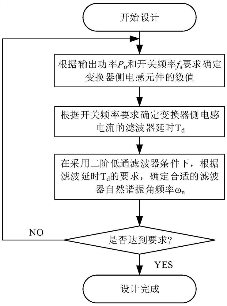
[0027] The present invention comprises the following steps:

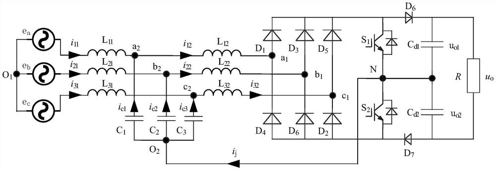
[0028] (1) According to the inductor current i of each phase on the converter side 12 i 22 and i 32 (Theoretical steady state i 12 i 22 and i 32 In addition to the phase difference of 120°, it has approximately the same waveform) to present a critical continuous state under the required load, according to Calculate the inductance value of the converter side of each phase (the inductance L of the three converter sides 12 , L 22 and L 32 have the same value L). In addition, T s for the desired switching period, V o is the rated voltage of the DC side, V cm is the AC side capacitance (C 1 、C 2 and C 3 ) peak voltage, I m Inductance L of each phase on the converter side 12 , L 22 and L 32 The peak value of the fundamental component of the current.

[0029] (2) According to Calculate the inductor current i for 12 i 22 and i 32 The delay of the filtered low-pass filter (these three currents will b...

Embodiment 2

[0037] combine Figure 1 to Figure 3 , the design method of the present invention is realized like this:

[0038] (1) According to the inductor current i of each phase on the converter side 12 i 22 and i 32 (Theoretical steady state i 12 i 22 and i 32 In addition to the phase difference of 120°, it has approximately the same waveform) to present the requirement of critical continuous state under the required load. At the unit power factor, the corresponding inductor current when the voltage phase is 90°:

[0039]

[0040] In the formula, I m is the peak value of the average value of the phase current.

[0041] The loop current equation in an inductor is:

[0042]

[0043] In the formula, V cm is the peak voltage of the capacitor on the AC input side.

[0044] The peak value of the average value of the phase current is:

[0045]

[0046] according to figure 1 , the DC side can be regarded as two Boost converters in series, and the voltages of the two DC cap...


PUM


Abstract

The invention discloses a three-phase two-switch rectifier filter inductance and hysteresis loop control switching frequency design method, step 1, the inductance current of each phase on the converter side is in a critical continuous state under the required load, and the phase inductance current on the converter side is calculated The inductance value L of the inductor; step 2, calculate the time delay T of the low-pass filter used for inductor current filtering d ; Step 3, if the frequency is f s =1 / T s The time delay of the signal passing through the second-order low-pass filter is T d , the corresponding phase delay satisfies: According to the second-order low-pass filter, the corner frequency is ω s The phase delay of the signal then calculates the natural resonant angular frequency ω of the second-order low-pass filter n ; Step 4: Under the condition of filter delay, the switching frequency f of the actual converter s The natural resonant angular frequency f using a low-pass filter n . The invention helps to reduce the harmonic distortion of the grid-side current, improves the sinusoidal degree of the grid-side current, and provides an engineering design method for switching frequency design under current hysteresis control.

Description

technical field [0001] The invention relates to a three-phase two-switch rectifier converter side filter inductance and a hysteresis loop control switching frequency design method, which belongs to the technical field of power electronics. Background technique [0002] Current hysteresis comparison control is usually used in systems that want to obtain good current control, but the actual switching frequency may not be easily controlled when using hysteresis control. Due to the influence of hysteresis width, too high switching frequency may cause damage to switching devices. The invention provides a three-phase two-switch rectifier filter inductance and a hysteresis control switching frequency design method. The three-phase two-switch rectifier has a good power factor correction function under the premise that the inductor current on the converter side needs to be intermittent or approximately in a critical continuous state (as the continuity of the inductor current on the c...

Claims


Application Information

Patent Timeline
Patent Type & Authority Patents(China)
IPC IPC(8): H02M1/12
CPCH02M1/12
Inventor 张镠钟彭辉王芳瑞游江
Owner HARBIN ENG UNIV
Why Eureka
Try Eureka