
Pulse oscillation device constructed and designed based on mathematical model

A technology of pulse oscillation and mathematical model, applied in the direction of injection devices, injection devices, etc., can solve the problems of unfavorable water pressure signal transmission and superposition, general jet impact performance, and general use effect, so as to promote cavitation effect and strengthen cavitation effect, not easy to crack

Inactive Publication Date: 2020-12-22
UNIV OF SCI & TECH BEIJING
View PDF6 Cites 12 Cited by
  • Summary
  • Abstract
  • Description
  • Claims
  • Application Information

AI Technical Summary

Problems solved by technology

[0002] The oscillating pulse jet is modulated by the principle of transient flow and hydroacoustics. It has the characteristics of pulse jet and cavitation jet. It is a simple structure, no additional external drive structure, no dynamic seal, and has a large variable pressure The impact effect of the new pulse jet with strong characteristics and strong cavitation is obviously better than that of the continuous jet, especially in the submerged state, the oscillating pulse jet has stronger destructive power than the ordinary jet, and it is a jet with great development prospects , has broad application prospects in the fields of mining rock breaking, oil drilling, ship cleaning, etc. At present, the oscillating pulse oscillators on the market have general jet impact performance, relatively unstable signal fluctuations, which are not conducive to the transmission and superposition of water pressure signals and It is prone to cracking problems, which leads to mediocre results. For this reason, a pulse oscillation device based on mathematical model construction and design is proposed to solve the above problems

Method used


Image

  • Pulse oscillation device constructed and designed based on mathematical model
  • Pulse oscillation device constructed and designed based on mathematical model
  • Pulse oscillation device constructed and designed based on mathematical model

Examples


Embodiment

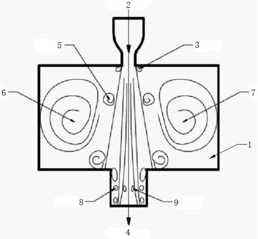
[0033] Please refer to Figure 1-14 As shown, a pulse oscillation device designed based on a mathematical model includes a housing 1, a jet inlet 2, a first discrete vortex 3, a jet outlet 4, a second discrete vortex 5, a first air bag 6, a first air bag The capsule 7, the first air bubble 8 and the second air bubble 9, the top of the housing 1 is fixed with a jet inlet 2, the bottom of the jet inlet 2 extends to the inside of the housing 1 and is connected with a jet outlet 4, the The tops on both sides of the jet outlet 4 are provided with a first discrete vortex 3, one side of the inner cavity of the casing 1 is provided with a first air bag 6, and the other side of the inner cavity of the casing 1 is provided with a second air bag 7. A second discrete vortex 5 is arranged between the first air bag 6 and the second air bag 7 and the jet outlet 4, and the bottom of the inner cavity of the jet outlet 4 is provided with a second air bubble 9, so A first air bubble 8 is provid...


PUM


Abstract

The invention discloses a pulse oscillation device constructed and designed based on a mathematical model, and relates to the technical field of pulse oscillators. The pulse oscillation device comprises a shell, a jet flow inlet, a first discrete vortex, a jet flow outlet, a second discrete vortex, a first air steam bag, a second air steam bag, first air bubbles and second air bubbles, and the jetflow inlet is fixedly formed in the top of the shell. According to the pulse oscillation device constructed and designed based on the mathematical model, the jet flow impact performance is high, thepulse signal mutability is high, the amplitude change is stable, the improvement on jet flow impact performance is facilitated, the characteristic of the stable pulse effect is achieved, an internal system is stable, large-scale vortexes existing in an oscillation cavity and the pulse pressure oscillation effect can cause vortex cavitation and oscillation cavitation formation in a self-oscillationcavity, and therefore the cavitation effect of the jet flow outlet is enhanced, the cavitation effect of the jet flow is effectively promoted, meanwhile, transmission and superposition of water pressure signals are facilitated, and the cracking problem is not prone to occurring.

Description

technical field [0001] The invention relates to the technical field of pulse oscillators, in particular to a pulse oscillation device designed based on mathematical models. Background technique [0002] The oscillating pulse jet is modulated by the principle of transient flow and hydroacoustics. It has the characteristics of pulse jet and cavitation jet. It is a simple structure, no additional external drive structure, no dynamic seal, and has a large variable pressure The impact effect of the new pulse jet with strong characteristics and strong cavitation is obviously better than that of the continuous jet, especially in the submerged state, the oscillating pulse jet has stronger destructive power than the ordinary jet, and it is a jet with great development prospects , has broad application prospects in the fields of mining rock breaking, oil drilling, ship cleaning, etc. At present, the oscillating pulse oscillators on the market have general jet impact performance, relat...

Claims


Application Information

Patent Timeline
IPC IPC(8): B05B1/34
CPCB05B1/341
Inventor 汪东李铁刘梅华赵晶王维华郭建行王栓林刘桂凤
Owner UNIV OF SCI & TECH BEIJING
Learn More