
Lower die displacement type continuous thin plate stamping device

A sheet metal stamping and displacement technology, applied in the field of mechanical processing, can solve the problems of operator's bodily injury, danger of metal sheet stamping device, structural design defects, etc., and achieve the effect of improving stability, improving quality, and efficient and safe stamping operation.

Inactive Publication Date: 2020-12-22
田文惠
View PDF1 Cites 0 Cited by
  • Summary
  • Abstract
  • Description
  • Claims
  • Application Information

AI Technical Summary

Problems solved by technology

In the current industrial production, stamping is basically manual operation, that is, by manually placing the sheet material on the base of the stamping equipment, and manipulating the stamping head to move to the position of the raw material, the stamping operation is performed, but the metal sheet stamping device has a certain The danger of the stamping equipment may cause injury to the operator's body when the metal sheet stamping process is performed manually
[0003] Chinese patent (notification number CN210996024U) discloses a sheet metal stamping device, although it can carry out stamping operations, but there are defects in structural design, resulting in deficiencies in safe operation, adjustment, and stable processing, resulting in poor processing quality ideal

Method used


Image

  • Lower die displacement type continuous thin plate stamping device
  • Lower die displacement type continuous thin plate stamping device
  • Lower die displacement type continuous thin plate stamping device

Examples


Embodiment 1

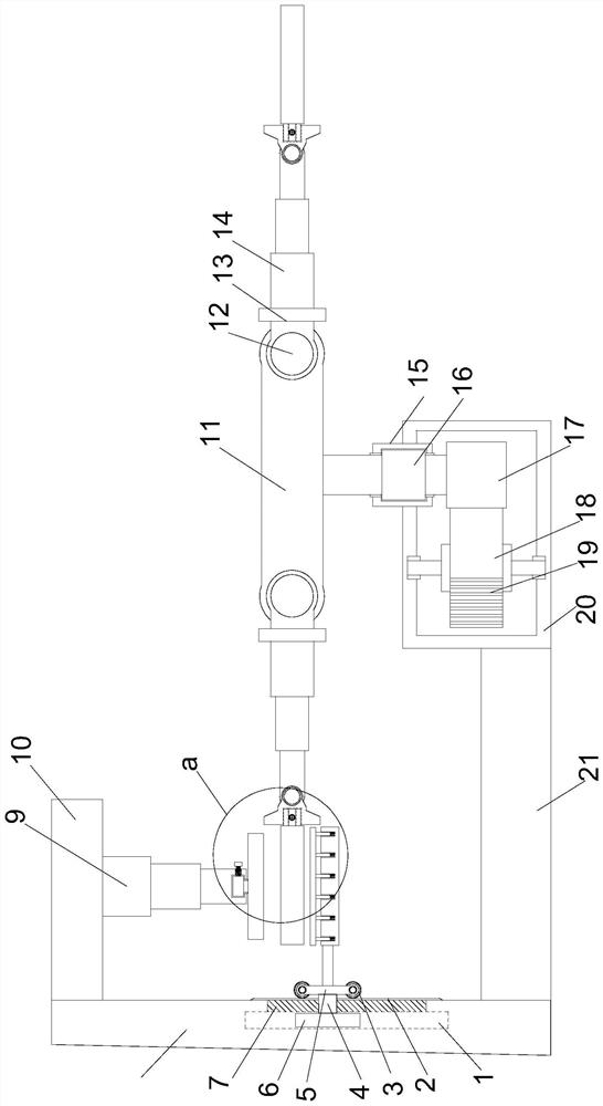
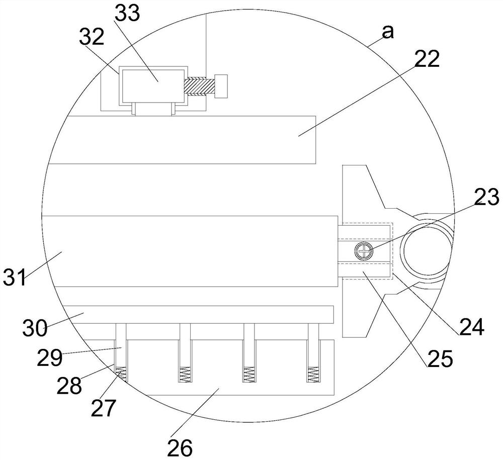
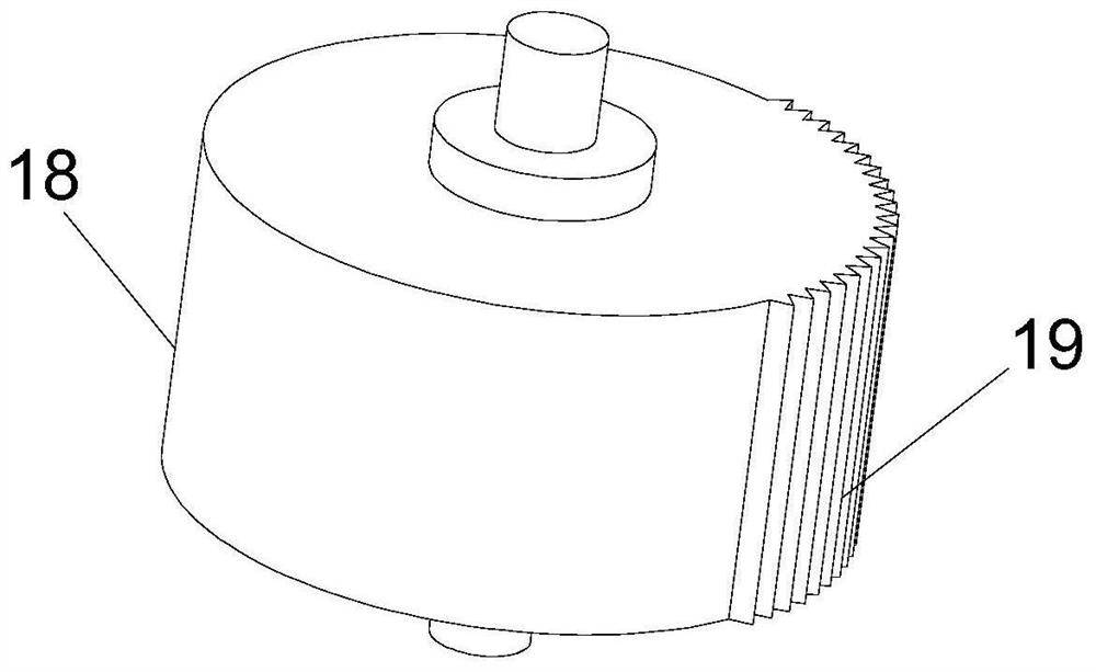
[0021] see Figure 1~3 , in an embodiment of the present invention, a lower die displacement type continuous thin plate stamping device includes a horizontally arranged support installation plate 21, a support installation column 8 is arranged vertically upward on the left end of the support installation plate 21, and the upper end of the support installation column 8 The top mounting plate 10 is arranged horizontally to the right, the right end of the support mounting plate 21 is vertically provided with a transmission installation cover 20, and the upper right end of the transmission installation cover 20 is vertically provided with a limit bearing sleeve 15, and the said matching limit bearing sleeve 15 is vertically arranged. The limit rotating shaft 16 is arranged vertically, the upper end of the limit rotating shaft 16 is horizontally provided with a steering mounting plate 11, the lower end of the limit rotating shaft 16 is coaxially provided with a steering gear 17, and...

Embodiment 2

[0024] On the basis of Embodiment 1, through the cooperation of the moving gear 3 and the moving rack 2, the lifting and lowering adjustment of the lifting installation plate 5 is realized, and then under the cooperation of the guiding installation column 6 and the guiding installation groove 1, a stable guiding lifting is realized, so that The position-limiting mounting plate 26 stops at a certain height. At this time, under the action of the return spring 27, the displacement guide column 29 extends out in cooperation with the displacement guide groove 28, realizing the support of the displacement support plate 30 to the lower template 31, and significantly improving the stamping process. stability, while improving the precision and quality of sheet metal stamping.


PUM


Abstract

The invention relates to the field of machining, in particular to a lower die displacement type continuous thin plate stamping device. The device comprises a horizontally-arranged supporting installation plate; a supporting installation column is vertically and upwardly arranged at the left end of the supporting installation plate; a top installation plate is horizontally and rightwardly arrangedat the upper end of the supporting installation column; a transmission installation cover is vertically arranged at the right end of the supporting installation plate; a limiting bearing sleeve is vertically arranged at the upper right end of the transmission installation cover; and a limiting rotating shaft is vertically arranged on the limiting bearing sleeve. Rotating displacement is achieved through periodic transmission, materials can enter an operation area periodically, the materials leaving the operation area can be taken out safely, and efficient and safe stamping operation is achieved. Meanwhile, the stamping height can be adjusted under the adjustment of rotation and stretching, use by different operators is convenient while stamping is convenient, and adaptive guiding lifting adjustments are achieved, so the stamping stability is remarkably improved, and the stamping quality is improved.

Description

technical field [0001] The invention relates to the field of mechanical processing, in particular to a lower die displacement type continuous sheet stamping device. Background technique [0002] Stamping processing is a production technology that uses the power of conventional or special stamping equipment to directly subject the sheet to deformation force and deform in the mold, so as to obtain product parts of a certain shape, size and performance. In the current industrial production, stamping is basically manual operation, that is, by manually placing the sheet material on the base of the stamping equipment, and manipulating the stamping head to move to the position of the raw material, the stamping operation is performed, but the metal sheet stamping device has a certain The stamping equipment may cause injury to the operator's body when the sheet metal stamping process is performed manually. [0003] Chinese patent (notification number CN210996024U) discloses a sheet ...

Claims


Application Information

Patent Timeline
Patent Type & Authority Applications(China)
IPC IPC(8): B21D22/02B21D37/06
CPCB21D22/02B21D37/06
Inventor 田文惠
Owner 田文惠
Learn More