
Mechanical lifting type construction machine transfer device

A technology for construction machinery and transfer devices, applied in hoisting devices, hoisting devices, lifting frames, etc., can solve the problems of consuming manpower and material resources, large manpower and material resources, wear and tear, etc., to improve its own strength and stability, and avoid tremors and shaking , the impact mitigation effect

Active Publication Date: 2020-12-22
WENZHOU POLYTECHNIC
View PDF5 Cites 1 Cited by
  • Summary
  • Abstract
  • Description
  • Claims
  • Application Information

AI Technical Summary

Problems solved by technology

[0004] Aiming at the deficiencies of the prior art, the present invention provides a mechanical lifting type construction machinery transfer device, which solves the problem of directly moving the main body of the mechanical equipment proposed in the above background technology, which not only needs to consume a lot of manpower and material resources, but also for some more precise Mechanical equipment is also very easy to cause bumps, scratches, wear and other damage during the transfer process, and most of the auxiliary transfer devices are simple transport pallets or direct manual transfer. This method consumes a lot of manpower and material resources, and the efficiency is low.

Method used


Image

  • Mechanical lifting type construction machine transfer device
  • Mechanical lifting type construction machine transfer device
  • Mechanical lifting type construction machine transfer device

Examples


Embodiment Construction

[0027] The following will clearly and completely describe the technical solutions in the embodiments of the present invention with reference to the accompanying drawings in the embodiments of the present invention. Obviously, the described embodiments are only some, not all, embodiments of the present invention.

[0028] In the description of the present invention, unless otherwise stated, the meaning of "plurality" is two or more; the terms "upper", "lower", "left", "right", "inner", "outer" , "front end", "rear end", "head", "tail", etc. indicate the orientation or positional relationship based on the orientation or positional relationship shown in the drawings, and are only for the convenience of describing the present invention and simplifying the description, rather than Nothing indicating or implying that a referenced device or element must have a particular orientation, be constructed, and operate in a particular orientation should therefore not be construed as limiting ...


PUM


Abstract

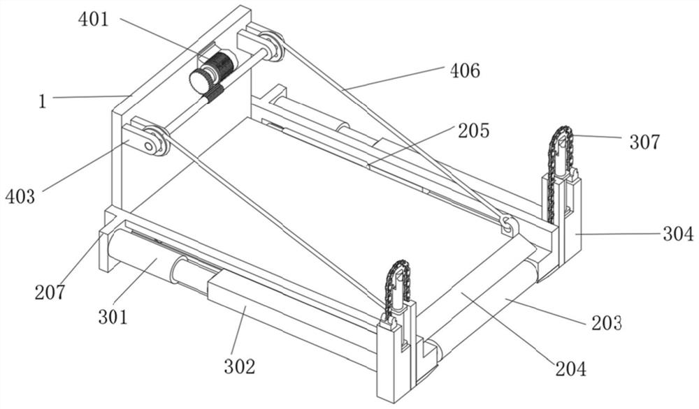
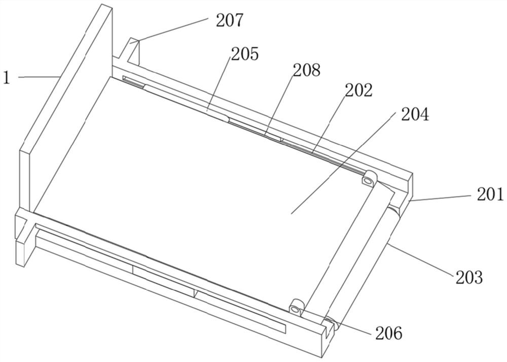
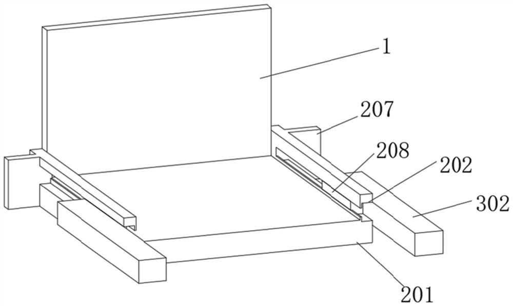
The invention discloses a mechanical lifting type construction machine transfer device, and relates to the technical field of mechanical equipment transportation. The device comprises a mounting plate, a bottom assembly, a lifting assembly and a turbine assembly. A bottom frame is mounted at the bottom of the bottom assembly, the bottom assembly is positioned on the front side of the mounting plate, and through grooves are formed in both the two sides of the bottom frame. A roller is transversely arranged in the middle of the front side of the bottom frame, movable blocks are arranged in the through grooves, a movable plate is arranged between the two movable blocks, the movable plate and the movable blocks are connected through pin roll rods, lifting ring seats are fixed to the upper surface of the left side and the upper surface of the right side of the front side of the movable plate respectively, and side wing plates are fixed to both the left side and the right side of the rear side of the bottom frame. Air cylinders are installed on the two sides of the lifting assembly, the lifting assembly is located on the two sides of the bottom assembly, a motor is installed on the top of the turbine assembly, and the turbine assembly is located above the front side of the mounting plate. With the mechanical lifting type construction machine transfer device, manpower and material resources needed in the machine transportation process can be reduced, the structure is simple, and the efficiency is high.

Description

technical field [0001] The invention relates to the technical field of mechanical equipment transportation, in particular to a mechanical lifting construction machinery transfer device. Background technique [0002] In recent years, various light and heavy industries and construction industries have developed rapidly, and all kinds of machinery and equipment have also developed rapidly and their types have gradually increased. However, in many cases, it is necessary to transfer machinery and equipment from one place to another, but it is limited to the structural problems of many machinery and equipment. , directly moving the main body of the mechanical equipment not only consumes a lot of manpower and material resources, but also easily causes bumps, scratches, wear and other damage during the transfer process for some more sophisticated mechanical equipment, and most of the auxiliary transfer devices are simple transportation Tray or direct manual transfer, this method con...

Claims


Application Information

Patent Timeline
Patent Type & Authority Applications(China)
IPC IPC(8): B66F7/04B66F7/28B66D1/12B66D1/28
CPCB66F7/04B66F7/28B66D1/12B66D1/28
Inventor 谷志阳
Owner WENZHOU POLYTECHNIC
Learn More