
Incubator capable of automatically removing condensed water

A technology of condensate water and incubator, which is applied to specific-purpose bioreactors/fermenters, biochemical instruments, biochemical equipment and methods, etc., can solve the problems of condensate water contamination of culture medium, etc. Evenly distributed effect

Active Publication Date: 2020-12-22
江苏保捷舒药研医药销售有限公司
View PDF4 Cites 2 Cited by
  • Summary
  • Abstract
  • Description
  • Claims
  • Application Information

AI Technical Summary

Problems solved by technology

[0005] The purpose of the present invention is to provide a kind of incubator that can remove condensed water in time and can automatically remove condensed water to solve the problem that condensed water is easy to contaminate the culture medium on the inner wall of most traditional incubators

Method used


Image

  • Incubator capable of automatically removing condensed water
  • Incubator capable of automatically removing condensed water
  • Incubator capable of automatically removing condensed water

Examples


Embodiment 1

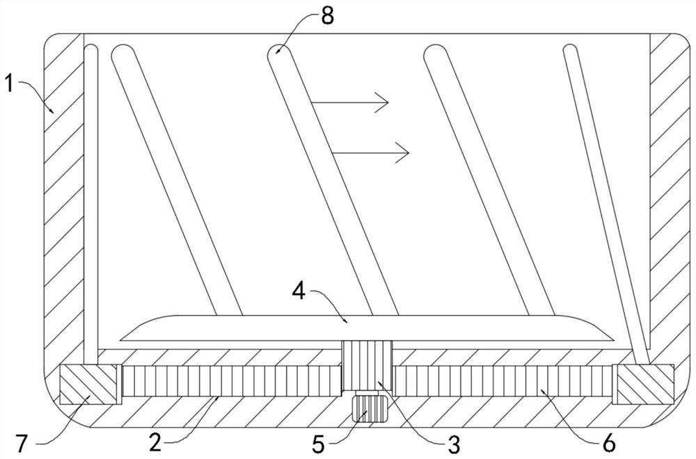
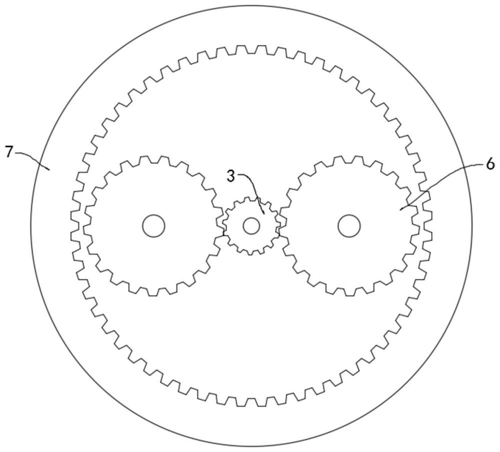
[0026] Such as Figure 1-2 As shown, a constant temperature box that can automatically remove condensed water includes a horizontally arranged box body 1, a transmission chamber 2 is provided in the lower side wall of the box body 1, and a central gear 3 is rotatably connected to the center of the transmission chamber 2. The central gear The upper end of 3 extends into the box body 1 and is fixedly connected with a carrier plate 4 on which the culture dish is placed.

[0027] A motor 5 is fixedly installed at the lower end of the transmission chamber 2, and the motor 5 is coupled with a controller (not shown in the figure), the controller will control the opening and closing of the motor 5 according to the amount of condensed water inside the box body 1, and the output terminal of the motor 5 is connected to the The lower side wall of the central gear 3 is coaxially fixedly connected.

[0028] Both sides of the central gear 3 are meshed with a planetary gear 6, and the two pl...

Embodiment 2

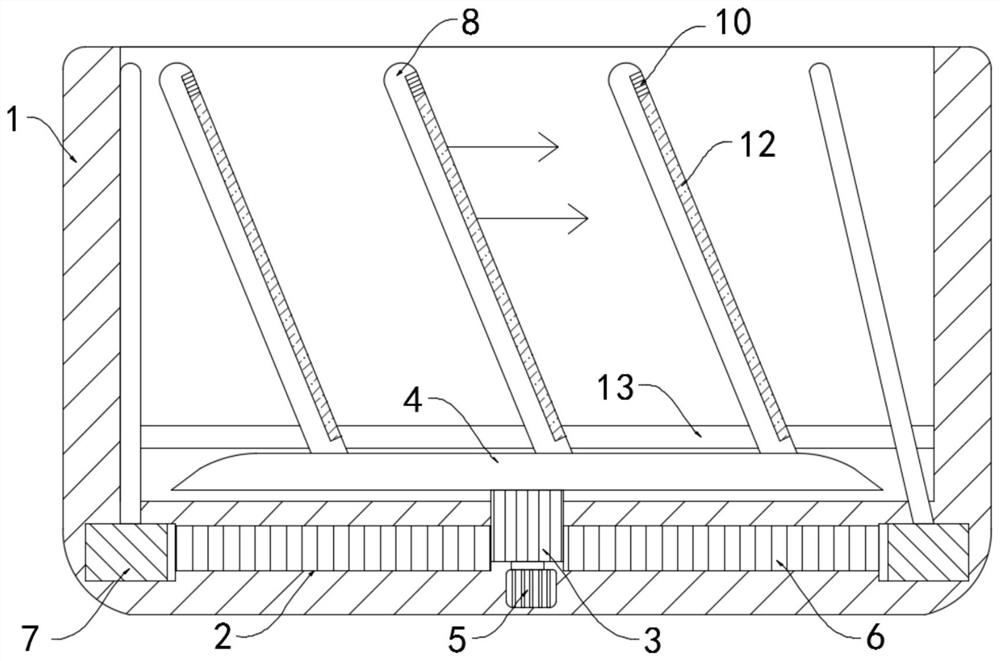
[0034] Such as Figure 3-4 As shown, the difference between this embodiment and Embodiment 1 is that a placement groove 9 is provided on the side wall of the scraper strip 8, and an elastic corrugated tube 10 is fixedly connected to the inner top surface of the placement groove 9. It should be noted that the elastic corrugated pipe The tube 10 contains silver bromide particles and is transparent.

[0035] The lower end of the elastic bellows 10 is fixedly connected with a push block 11, and the lower end of the push block 11 is provided with a water-absorbing strip 12, which is a sponge product, and the water-absorbing strip 12 is placed in the placement groove 9. It should be noted that the placement groove 9 The notch is set smaller than the bottom of the groove, and the water-absorbing strip 12 is limited and fixed to prevent the water-absorbing strip 12 from slipping off from the placement groove 9 in the process of being squeezed.

[0036] The inner wall of the box body ...


PUM


Abstract

The invention belongs to the field of biological culture, and particularly relates to an incubator capable of automatically removing condensed water. The incubator comprises a horizontally arranged incubator body, a transmission cavity is arranged in the lower side wall of the incubator body, the center of the transmission cavity is rotatably connected with a central gear, the upper end of the central gear extends into the incubator body and is fixedly connected with a bearing disc, a motor is fixedly installed at the lower end of the transmission cavity, the output end of the motor is coaxially and fixedly connected with the lower side wall of the central gear, planetary gears are connected to the two sides of the central gear in an engaged mode and rotationally connected with the transmission cavity, an inner gear ring is rotationally connected into the transmission cavity, and the two planetary gears are sleeved with the inner gear ring, and the inner gear ring is in engaged connection with the two planetary gears. When an incubator cover of the incubator is opened, an elastic corrugated pipe can be filled with gas, a push block is extruded downwards to extrude water on a waterabsorption strip, the elastic corrugated pipe can shrink when the incubator cover is closed, and the extruded water absorption strip can be unfolded at the moment to continue to absorb condensate water on the side wall of the incubator body.

Description

technical field [0001] The invention belongs to the field of biological cultivation, in particular to an incubator capable of automatically removing condensed water. Background technique [0002] In the field of biochemical industry, it is often necessary to cultivate various microorganisms, that is, with the help of artificially prepared culture media and artificially created culture conditions, it is a means of rapid growth and reproduction of certain microorganisms. During the cultivation process of microorganisms, the temperature and humidity The adjustment of other conditions has more stringent requirements. [0003] In the process of microbial cultivation, it is often necessary to put the petri dish into the incubator. The temperature in the incubator is generally higher than the ambient temperature, and most of the traditional incubators have only one layer of heat insulation board on the side wall. Condensed water is easy to condense on the surface, and the accumula...

Claims


Application Information

Patent Timeline
Patent Type & Authority Applications(China)
IPC IPC(8): C12M1/00C12M1/38
CPCC12M39/00C12M41/12
Inventor 赵萍
Owner 江苏保捷舒药研医药销售有限公司
Learn More