Telescopic water guide device of railroad bridge and use method thereof
A technology for bridges and railways, applied in the field of telescopic water guiding devices, which can solve the problems of difficult bridge replacement, long maintenance time, and short service life, and achieve the effects of reducing maintenance frequency, increasing service life, and increasing service life
- Summary
- Abstract
- Description
- Claims
- Application Information
AI Technical Summary
Problems solved by technology
Method used
Image
Examples
Embodiment 1
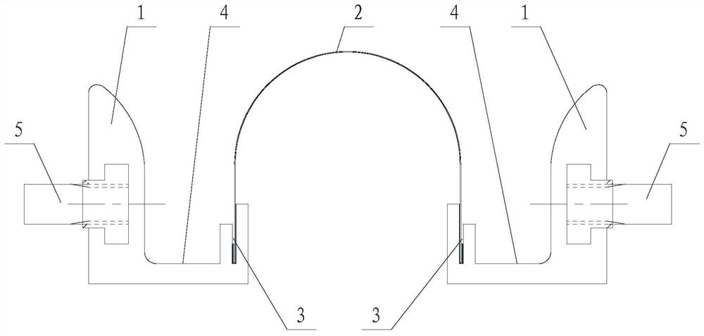
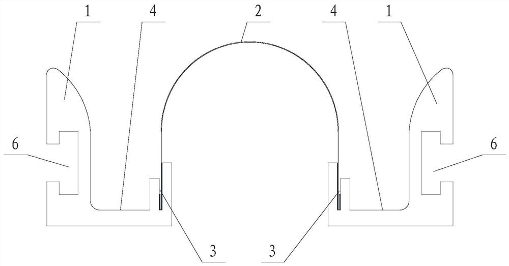
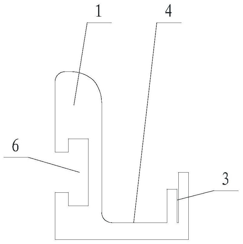
[0029] Such as Figure 1~3 As shown, the telescopic water guiding device of this embodiment includes a steel frame 1, a stainless steel plate 2 and an anchor assembly 5, wherein the steel frame 1 is installed on the opposite surfaces of the two bridges with gaps, and one side of the steel frame 1 passes through the anchor assembly. 5 is fixed on the bridge, and the other side is provided with draw-in groove 3, is provided with the storage tank 4 that is used for guiding water on the steel frame 1 between both sides, and the groove surface of the storage tank 4 of this embodiment is an inclined plane, and the storage tank 4 There is a water collector at the end. Both sides of the stainless steel plate 2 are respectively inserted into the slots 3 fixed to the steel frame 1 on the two bridges. The slots 3 are filled with glue. The stainless steel plate 2 is located below the gap left between the two bridges. The stainless steel plate 2 The top surface is curved.
[0030] The en...
Embodiment 2
[0035] Such as Figure 4~6 As shown, the difference between the telescopic water guiding device of the present embodiment and the first embodiment is that: the steel frame 1 of the present embodiment and the bridge contact surface are provided with a ladder 7; correspondingly, the left end beam 8 and the right end beam 9 are provided with The seam corresponding to step 7, such as Figure 8 As shown; during installation, the ladder on the steel frame 1 is clamped on the notch of the left end beam 8 or the right end beam 9, and then the anchor component 5 is fixedly connected with the left end beam 8 or the right end beam 9. or as Figure 9 As shown, the position where the steel frame 1 is installed on the left end beam 8 and the right end beam 9 is provided with an "L"-shaped groove on the end surface, and a stop is set above the side of the groove; the ladder on the side of the steel frame 1 is stuck on the left end beam 8 or the seam of the right end beam 9, the bottom is a...
PUM
 Abstract
Description
Claims
Application Information
 - R&D
- Intellectual Property
- Life Sciences
- Materials
- Tech Scout
- Unparalleled Data Quality
- Higher Quality Content
- 60% Fewer Hallucinations
Browse by: Latest US Patents, China's latest patents, Technical Efficacy Thesaurus, Application Domain, Technology Topic, Popular Technical Reports.
© 2025 PatSnap. All rights reserved.Legal|Privacy policy|Modern Slavery Act Transparency Statement|Sitemap|About US| Contact US: help@patsnap.com


