Eureka AIR delivers breakthrough ideas for toughest innovation challenges, trusted by R&D personnel around the world.

Cross-shaped inserting structure for fabricated shear wall

A plug-in structure and shear wall technology, applied in the direction of structural elements, walls, building components, etc., can solve the problems of complicated grouting sleeve connection technology, hidden safety hazards, and heavy shear wall bearing, etc. The effect of improving installation speed and stable stability

Pending Publication Date: 2020-12-22
GOLD MANTIS FINE DECORATION TECH SUZHOU CO LTD
View PDF0 Cites 0 Cited by
  • Summary
  • Abstract
  • Description
  • Claims
  • Application Information

AI Technical Summary

Problems solved by technology

[0003] Compared with the cast-in-place form, the prefabricated shear wall has the advantages of high production efficiency, good engineering quality, easy technology integration, resource saving, and environmental protection. However, the gap between the existing prefabricated shear wall and the wall The main connection method is grouting sleeve connection, and the grouting sleeve connection technology is also becoming mature. However, the grouting sleeve connection technology is complicated and has high requirements for grouting sleeves, grouting materials and other materials. It is difficult to quickly and completely assemble the prefabricated shear wall. When assembling the roof on the top of the shear wall, because there is no good decompression design, the shear wall performs a good decompression operation on the roof, which may easily cause the shear wall to bear the load If it is too large, there will be safety hazards in future use

Method used


Image

  • Cross-shaped inserting structure for fabricated shear wall
  • Cross-shaped inserting structure for fabricated shear wall
  • Cross-shaped inserting structure for fabricated shear wall

Examples


Embodiment Construction

[0027] The following will clearly and completely describe the technical solutions in the embodiments of the present invention with reference to the accompanying drawings in the embodiments of the present invention. Obviously, the described embodiments are only some, not all, embodiments of the present invention.

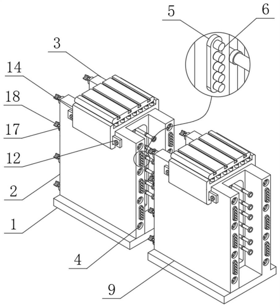
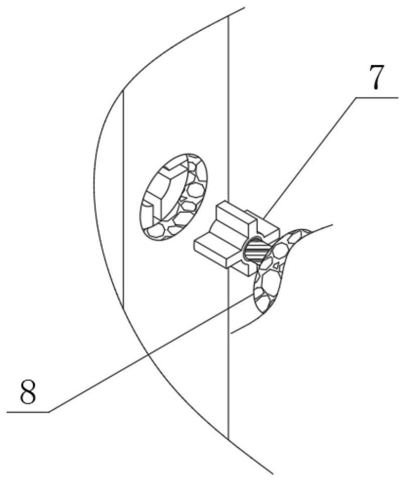
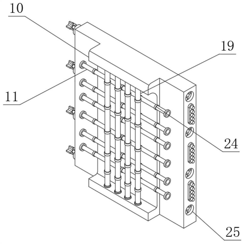
[0028] see Figure 1 to Figure 6 , the present invention provides a technical solution: a cross plug-in structure for a prefabricated shear wall, including a bottom plate 1, the upper surface of the bottom plate 1 is fixedly connected with a first shear wall 2 and a second shear wall in sequence from left to right Wall 3, one side of the second shear wall 3 is provided with a second socket slot 25, the other side of the first shear wall 2 is fixedly connected with a second sealing block 17, and one end of the second sealing block 17 is fixedly connected with The second plug-in block 18, one side of the first shear wall 2 is provided with the first plug-in slot 4, one...


PUM


Abstract

The invention discloses a cross-shaped inserting structure for a fabricated shear wall. The cross-shaped inserting structure comprises a bottom plate, a first shear wall, a second shear wall, a firstinserting groove, a limiting block, a limiting column and a first inserting block, wherein one end of the first inserting block is fixedly connected with a first sealing block, and one end of the first sealing block is fixedly connected with a third shear wall; and one end of the second shear wall is fixedly connected with a steel bar frame, and the inner side wall of the steel bar frame is fixedly connected with a first steel bar column. The cross-shaped inserting structure for the fabricated shear wall has the main advantages that the shear wall structure is provided, in the assembling process of the shear wall, an installation person aligns and inserts the first inserting block into the first inserting groove firstly, at the moment, the limiting block and a limiting groove can help thefirst shear wall and the third shear wall to be assembled in a more attached mode, and through the design, the attaching degree between wall bodies after assembling is higher while installation is easy, convenient and fast.

Description

technical field [0001] The invention relates to the technical field of construction equipment, in particular to a cross plug-in structure for a prefabricated shear wall. Background technique [0002] The construction methods of shear walls generally have two forms: cast-in-place and assembly. Cast-in-place is a traditional construction method that requires mold fixing, that is, by assembling templates on site, and then pouring concrete; assembly is the main way to realize the modern industrialization of buildings. The structural form is mainly to prefabricate the prefabricated shear wall in the factory and reserve the corresponding connecting device. After installing the upper and lower prefabricated shear walls in place at the construction site, they can be reliably connected through the connecting device. [0003] Compared with the cast-in-place form, the prefabricated shear wall has the advantages of high production efficiency, good engineering quality, easy technology in...

Claims


Application Information

Patent Timeline
Patent Type & Authority Applications(China)
IPC IPC(8): E04B2/00E04B1/61E04C5/06
CPCE04B1/612E04B2/00E04C5/0636
Inventor 迟玉华黄强王雨马子腾沈威张海龙孙玲燕耿燕鲁迎
Owner GOLD MANTIS FINE DECORATION TECH SUZHOU CO LTD
Why Eureka
Eureka Blog
Learn More