Constant-pressure and constant-quantity type swab and constant-pressure and constant-quantity swabbing method

A technology of pumping and central pipe, which is applied in the field of liquid drainage and swabbing equipment for oil testing in low-permeability oilfields. It can solve the problems of difficulty in salvaging the wellbore, high cost, and poor effect, and achieve high-efficiency salvage.

Pending Publication Date: 2020-12-22
BC P INC CHINA NAT PETROLEUM CORP +1
View PDF0 Cites 0 Cited by
  • Summary
  • Abstract
  • Description
  • Claims
  • Application Information

AI Technical Summary

Problems solved by technology

It is costly and time-consuming to take out rubber cartridge fragments or reverse circulation to wash the well after pulling up the swabbing string, and it will also affect the physical properties of th

Method used


Image

  • Constant-pressure and constant-quantity type swab and constant-pressure and constant-quantity swabbing method
  • Constant-pressure and constant-quantity type swab and constant-pressure and constant-quantity swabbing method

Examples


Embodiment 1

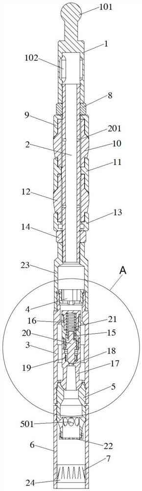
[0031] refer to figure 1 , the embodiment of the present invention proposes a constant pressure and constant volume drawer, including: an upper joint 1, a sealing assembly, a valve body 3, a valve core assembly and an overshot 6; the upper end of the upper joint 1 is a blind end, and a ball is connected Connecting head 101, the inner part of the lower end of upper joint 1 is connected with central pipe 2, and the side wall of upper joint 1 is radially provided with a plurality of first liquid outlet holes 102; There are a plurality of communication holes 201 connected to the inside of the sealing assembly; the valve body 3 is cylindrical, the upper end of the valve body 3 is directly or indirectly connected to the lower end of the central tube 2, and the inner side of the upper end of the valve body 3 is provided with an orifice cover 4 , the inner side of the lower end of the valve body 3 is connected with a ball seat nipple 5, and the ball seat nipple 5 conducts up and down;...

Embodiment 2

[0037] refer to figure 1 , on the basis of Example 1, the sealing assembly includes an upper back cap 8, an upper steel bowl 9, an upper rubber cylinder 10, a middle steel bowl 11, a lower rubber cylinder 12, a lower The steel bowl 13 , the lower back cap 14 , and a plurality of communication holes 201 are respectively connected to the inner sides of the upper rubber cylinder 10 and the lower rubber cylinder 12 .

[0038] When the constant pressure and constant volume pump is lifted up, the lower end of the valve core assembly blocks the upper port of the ball seat nipple 5 under its own gravity, and the liquid on the upper part of the constant pressure and constant volume pump will enter the upper port through a plurality of first liquid outlet holes 102. In the joint 1 and the central pipe 2, after entering the inner side of the upper rubber cylinder 10 and the lower rubber cylinder 12 through a plurality of communication holes 201, the hydraulic pressure will make the upper...

Embodiment 3

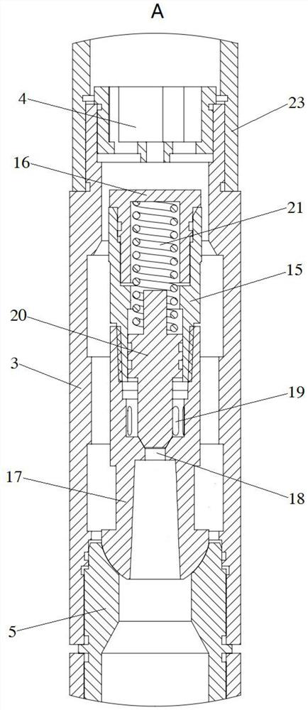
[0040] refer to figure 1 and figure 2 , on the basis of Embodiment 3, the outer side of the lower port of the lower spool 17 is provided with an outer arc surface, and the inner side of the upper port of the ball seat nipple 5 is provided with an inner arc surface, and the outer arc surface and the inner arc faces match.

[0041] Because there is an annular gap between the valve core assembly and the inner side wall of the valve body 3, the valve core assembly will be in an inclined state in the valve body 3, and the lower valve core 17 at the lower end of the valve core assembly passes through the outer arc surface and the ball seat. The inner arc surface of the upper port of the pup joint 5 is kept in sealing contact.


PUM


Abstract

The invention provides a constant-pressure and constant-quantity type swab and a constant-pressure and constant-quantity swabbing method. The constant-pressure and constant-quantity type swab comprises an upper joint, a sealing assembly, a valve body, a valve element assembly and a fishing socket; the upper end of the upper joint is connected with a ball connector, a center pipe is connected intothe lower end of the upper joint, and a first liquid outlet hole is formed in the side wall of the upper joint; the sealing assembly sleeves the periphery of the central pipe; the upper end of the valve body is directly or indirectly connected to the lower end of the central pipe, a pore plate cover is arranged on the inner side of the upper end of the valve body, and a ball seat short section isconnected to the inner side of the lower end of the valve body; the valve element assembly is arranged between the pore plate cover in the valve body and an upper end opening of the ball seat short section, an annular gap is formed between the valve element assembly and the inner side wall of the valve body, and the upper end opening of the ball seat short section is blocked by the valve element assembly under the action of gravity; and the fishing socket is connected to the outer side of the lower end of the ball seat short section, and a barb elastic piece is arranged on the inner side wallof the lower end of the fishing socket. The constant-pressure and constant-quantity swabbing method is implemented by adopting the constant-pressure and constant-quantity type swab.

Description

technical field [0001] The invention relates to the field of liquid drainage and swabbing equipment for oil testing operations in low-permeability oilfields, in particular to a constant-pressure and constant-volume pump and a constant-pressure and constant-volume swabbing method thereof. Background technique [0002] At present, hydraulic pumps are used in the oil well testing operation site to carry out oil testing operations, but during the pumping process, due to the quality of the rubber cartridges matching the pumps, improper operation by the operator, deep submersion or rough inner wall of the tubing, etc. It is very easy to cause the suction rubber tube to fall off in small pieces or in pieces and fall into the oil pipe. Continue the pumping operation, and the fallen rubber cartridge fragments float on the liquid surface, making it difficult for the pump to enter the liquid surface to extract the liquid. When the pumping rubber cartridge falls off too much, it is eas...

Claims


Application Information

Patent Timeline
IPC IPC(8): E21B43/00E21B31/18E21B34/06
CPCE21B43/00E21B31/18E21B34/06
Inventor 田军王国锋侯俊耀晏军雷璠徐锋波雷迎福魏晨田永峰潘生俊张强生王凡徐睿毛亚伟
Owner BC P INC CHINA NAT PETROLEUM CORP
Why Eureka
Try Eureka