Supercharge Your Innovation With Domain-Expert AI Agents!

Smoke exhaust fan

A fume exhaust fan and exhaust pipe technology, used in mechanical equipment, oil fume removal, machine/engine, etc., can solve the problems of difficult cleaning of the attachments on the inner wall of the pipe, affecting the rotation speed of the fan, and troublesome maintenance, so as to facilitate the overall management of the equipment. , The effect of maintaining smoke exhaust efficiency

Inactive Publication Date: 2020-12-22
刘天赐
View PDF0 Cites 1 Cited by
  • Summary
  • Abstract
  • Description
  • Claims
  • Application Information

AI Technical Summary

Problems solved by technology

[0004] Aiming at the deficiencies in the prior art, the purpose of the present invention is to provide a smoke exhaust fan to solve the problem that during the use of the existing smoke exhaust fan, because the smoke will be mixed with a lot of oil, gas and dust impurities, this part of the oil and gas will be attached. It is attached to the inner wall and has a certain degree of viscosity. In the long run, it will affect the rotation speed of the fan. The attachment on the inner wall of this part of the pipe is difficult to clean, and it will cause a lot of trouble for later maintenance.

Method used


Image

  • Smoke exhaust fan
  • Smoke exhaust fan
  • Smoke exhaust fan

Examples


no. 1 example

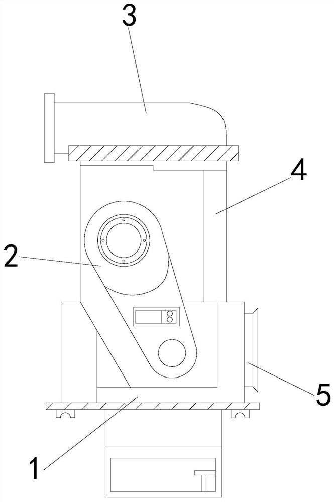
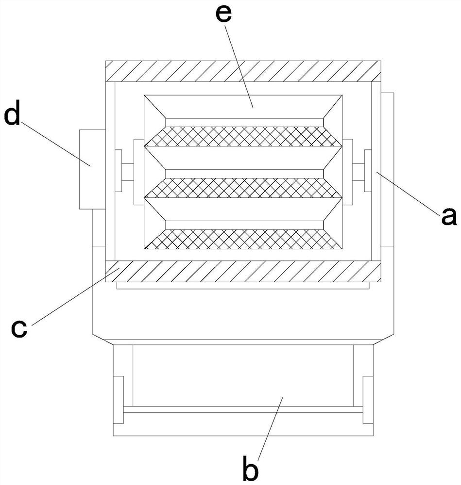
[0026] see Figure 1-Figure 4 , the present invention provides a smoke exhaust fan technical solution: its structure includes: a blower body 1, a power wheel set 2, a smoke exhaust pipe 3, a joint upper cylinder 4, and a smoke inlet pipe 5, and the smoke inlet pipe 5 is installed on the fan The front end of the blower body 1 is fastened with the blower body 1, and the side of the blower body 1 is provided with a power wheel set 2, and the power wheel set 2 is locked with the blower body 1, and the top of the blower body 1 is provided with There is a connection upper cylinder 4, the connection upper cylinder 4 is welded with the blower body 1, the upper end of the connection upper cylinder 4 is provided with a smoke exhaust pipe 3, the smoke exhaust pipe 3 is locked with the connection upper cylinder 4, and the air blower The cylinder body 1 includes a side guide plate device a, a collection bucket device b, an assembly frame c, a linkage shaft wheel d, and a fan guide wheel e....

no. 2 example

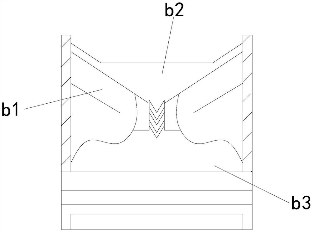
[0031] see Figure 5-Figure 6 , the present invention provides a smoke exhaust fan technical solution: its structure includes: the separation spreading device a1 includes a shaft scraping roller a11, a bearing frame a12, a concave dial a13, a scraper blade a14, and a fitting rod a15, the The concave dial a13 is installed on the end of the fitting rod a15 and welded with the fitting rod a15. The inner side of the fitting rod a15 is provided with a tooth scraper a14, and the scraper a14 is locked with the fitting rod a15. A bearing frame a12 is provided at the front end of the closing rod a15, and the bearing frame a12 is fastened to the laminating rod a15, and the inner side of the concave dial a13 is provided with a scraping roller a11 and is fastened to the scraping roller a11.

[0032] The shaft scraping roller a11 includes a built-in rod a111, an arc-shaped scraper a112, and a fixed head a113. The end of the a111 is locked with the built-in rod a111, and the scraping shaft...


PUM


Abstract

The invention discloses a smoke exhaust fan. The fan structurally comprises an air duct machine body, a power wheel set, a smoke exhaust pipe, an upper connecting cylinder and a smoke inlet pipe; andthe smoke inlet pipe is installed at the front end of the air duct machine body and buckled with the air duct machine body. When the smoke exhaust fan is used, problems can be avoided through the arranged mechanisms that in the using process of the smoke exhaust fan, due to the fact that many oil gas dust impurities are mingled in smoke, part of oil gas can be attached to the inner wall and has certain viscosity, the rotating speed of the fan can be affected over time, attachments on the inner wall of the part of pipeline are difficult to clean, and great trouble can be caused for later maintenance; through mutual cooperation of separation spreading plate devices, the attachments on the inner wall can be synchronously scraped off, the smoke exhaust efficiency of a fan wheel is effectivelykept, meanwhile, the attachments in a channel are collected in a unified mode under mutual cooperation of collection hopper devices, and overall management of the smoke exhaust fan is more convenient.

Description

technical field [0001] The invention relates to a smoke exhaust fan, which belongs to the field of smoke exhaust fan equipment. Background technique [0002] The smoke exhaust fan is a machine that can quickly remove the peculiar smell, high temperature, and oily smoke generated during food processing in the kitchen. The machine is characterized by good high temperature resistance and high efficiency. [0003] The existing technology has the following disadvantages: During the use of the exhaust fan, because the flue gas will be mixed with a lot of oil, gas and dust impurities, this part of the oil and gas will adhere to the inner wall and have a certain viscosity, which will affect the fan in the long run. If the rotation speed is high, the attachment on the inner wall of this part of the pipe is difficult to clean, which will cause a lot of trouble for later maintenance. Contents of the invention [0004] Aiming at the deficiencies in the prior art, the purpose of the p...

Claims


Application Information

Patent Timeline
Patent Type & Authority Applications(China)
IPC IPC(8): F04D29/40F04D29/70F24C15/20
CPCF04D29/403F04D29/701F24C15/20
Inventor 刘天赐
Owner 刘天赐
Features
  • R&D
  • Intellectual Property
  • Life Sciences
  • Materials
  • Tech Scout
  • Unparalleled Data Quality
  • Higher Quality Content
  • 60% Fewer Hallucinations
Learn More