A high-efficiency heat transfer with low no x exhaust burner
A burner, high-efficiency technology, applied in the direction of burner, gas fuel burner, combustion type, etc., can solve the problem of high NOx emissions, achieve the effect of reducing NOx emissions, reducing NOx, and ensuring smoke exhaust efficiency
- Summary
- Abstract
- Description
- Claims
- Application Information
AI Technical Summary
Problems solved by technology
Method used
Image


Examples
Embodiment 1
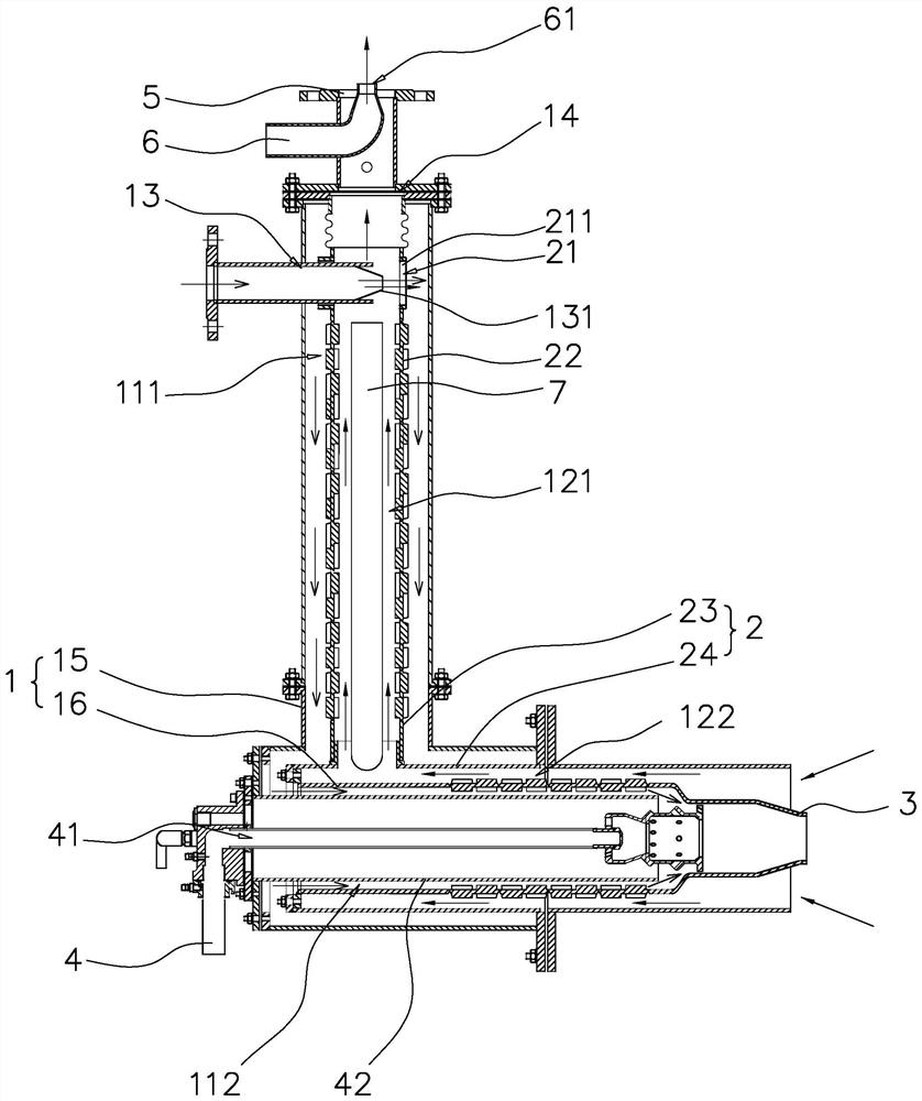
[0044] refer to figure 1 , a high-efficiency heat exchange low NOx emission burner includes a shell 1 , a gas guide pipe 2 , a gas element 3 and a gas pipe 4 . The gas element 3 may be a device capable of providing conditions for combustion such as a combustion chamber, and the gas element 3 is used for mixing air and gas and burning the mixture of air and gas.
[0045] In the first embodiment, the housing 1 is generally arranged in an "L" shape, and the gas guide pipe 2 is generally arranged in an "L" shape suitable for the housing 1 . The casing 1 is sheathed on the outside of the gas guide pipe 2 .
[0046] The casing 1 has a gas flow space for gas flow, and the gas flow space is divided into a gas flow channel 41 , an intake flow channel 11 and a smoke exhaust flow channel 12 which are isolated from each other. The gas flow passage 41 has a gas inlet end and a gas outlet end, and the gas outlet end of the gas flow passage 41 is connected to the gas element 3 so that the ...
Embodiment 2
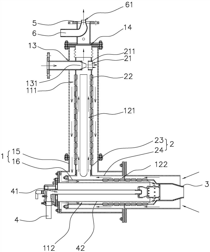
[0052] refer to figure 2 , the first difference between the second embodiment and the first embodiment mainly lies in that the positions of the air intake flow channel 11 and the smoke exhaust flow channel 12 are exchanged.
[0053] In the second embodiment, the housing 1 is generally arranged in an "L" shape, and the gas guide pipe 2 is generally arranged in an "L" shape that matches the housing 1 .
[0054] The difference is that the casing 1 includes a first shell part 15 and a second shell part 16 fixedly arranged on the first shell part 15 . The gas element 3 is located at an end of the second casing 1 away from the first casing part 15 . The smoke exhaust port 14 is located on the end face of the first shell portion 15 away from the second shell portion 16, the air inlet 13 is located on the outer wall of the first shell portion 15 away from the end of the second shell portion 16, and the air inlet 13 is in the vertical direction It is close to the gas element 3 relat...
Embodiment 3
[0062] refer to image 3 The difference between the third embodiment and the second embodiment lies in the position of the outlet end of the air inlet nozzle 131 .
[0063] In the third embodiment, the gas outlet end of the air inlet nozzle 131 passes through the side wall of the gas guide pipe 2 , so that the gas outlet end of the air inlet nozzle 131 is located in the first smoke exhaust chamber 121 . The gas injected by the air intake nozzle 131 directly enters the first smoke exhaust chamber 121 , and passes through the smoke return flow channel on the side away from the air inlet 13 to enter the first air intake chamber 111 .
[0064] Correspondingly, in the third embodiment, the number of the smoke return pipe section 211 is one, that is, the number of the smoke return channel 21 is one. At this time, the gas ejected from the intake nozzle 131 directly enters the first smoke exhaust chamber 131 and enters the only smoke return pipe section 211, and the gas can take away...
PUM
 Abstract
Description
Claims
Application Information
 - R&D
- Intellectual Property
- Life Sciences
- Materials
- Tech Scout
- Unparalleled Data Quality
- Higher Quality Content
- 60% Fewer Hallucinations
Browse by: Latest US Patents, China's latest patents, Technical Efficacy Thesaurus, Application Domain, Technology Topic, Popular Technical Reports.
© 2025 PatSnap. All rights reserved.Legal|Privacy policy|Modern Slavery Act Transparency Statement|Sitemap|About US| Contact US: help@patsnap.com