A self-driven slewing bearing

A slewing bearing and self-driving technology, applied in the field of mechanical parts, can solve the problems of large volume and weight, large axial dimension, and high manufacturing cost of the whole machine, and achieve the effects of saving installation space, large power-to-weight ratio, and compact structure

Active Publication Date: 2021-08-31
马鞍山市方正机械制造有限责任公司
View PDF9 Cites 0 Cited by
  • Summary
  • Abstract
  • Description
  • Claims
  • Application Information

AI Technical Summary

Problems solved by technology

[0003] This combination method of fixedly connecting the slewing bearing and the reducer has the following disadvantages: First, the transmission device composed of two independent components, the slewing bearing and the reducer, has a complex structure and many parts, which is not only difficult to accurately Assembling, and it is necessary to add auxiliary parts that connect and fix the two parts, the manufacturing cost is relatively high; secondly, through the transmission device composed of two independent parts through the slewing bearing and the reducer, the volume and weight of the whole machine are large, and the axial dimension is also small. Larger, usually requires a larger installation space, it is not suitable for installation and application in some flat layout occasions, and at the same time increases the energy consumption of operation

Method used


Image

  • A self-driven slewing bearing
  • A self-driven slewing bearing
  • A self-driven slewing bearing

Examples


Embodiment Construction

[0017] The following will clearly and completely describe the technical solutions in the embodiments of the present invention with reference to the accompanying drawings in the embodiments of the present invention. Obviously, the described embodiments are only some, not all, embodiments of the present invention. Based on the embodiments of the present invention, all other embodiments obtained by persons of ordinary skill in the art without making creative efforts belong to the protection scope of the present invention.

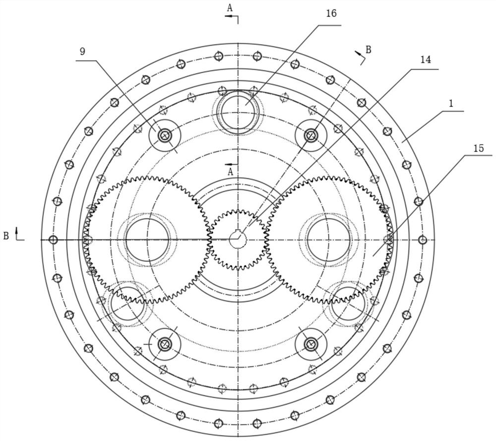
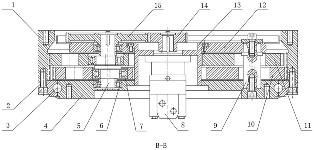
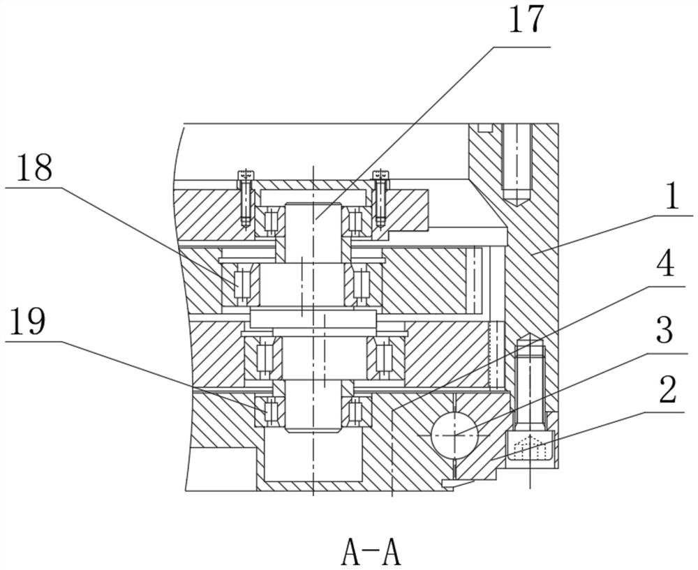
[0018] see Figure 1-3 , a self-driven slewing bearing, including a slewing bearing outer ring 2, a slewing bearing inner seat 4 is movably socketed inside the slewing bearing outer ring 2, and several A group of steel balls 3, the inner ring gear 1 is fixedly connected to the upper part of the slewing bearing outer ring 2, the motor support 13 is fixedly connected to the middle part of the slewing bearing inner seat 4, the hydraulic motor 8 is fixedly install...


PUM


Abstract

The invention relates to the technical field of mechanical parts, and discloses a self-driven slewing ring, which includes an outer ring of the slewing ring, an inner seat of the outer ring of the slewing ring is movable, and an inner seat of the slewing ring is movable. Several sets of steel balls are arranged at the joint, the inner ring gear is fixedly connected to the upper part of the outer ring of the slewing ring, and the motor support is fixedly connected to the middle part of the inner seat of the slewing ring. By setting the reduction mechanism in the inner ring gear, using the first translation chainring and the second translation chainring to directly drive the inner ring gear for rotary motion, the slewing bearing capable of bearing heavy loads and the reducer are combined to design, The integrated design of slewing bearing and reducer not only eliminates the independent slewing bearing and reducer connected with auxiliary parts through mechanical fixing, but also reduces the volume and weight of the device, and the whole machine has a compact structure, a large power-to-weight ratio of the equipment, and at the same time reduces the The axial dimension is especially suitable for applications where the equipment requires a flat layout.

Description

technical field [0001] The invention relates to the technical field of mechanical parts, in particular to a self-driven slewing bearing. Background technique [0002] In transmission devices such as construction machinery and solar tracking, it is usually necessary to use both a slewing mechanism and a speed change mechanism at the same time. At present, most slewing mechanisms use an independent slewing ring and a speed change mechanism to ensure that the slewing ring can work in the horizontal direction. Plane rotary motion, at the same time, the independent reducer realizes its speed change function. The slewing bearing and the reducer are two independent parts, and the two parts are connected and fixed by mechanical means. Among them, the slewing bearing is a new type of mechanical component, which is composed of inner and outer rings, rolling elements, etc. The slewing bearing is a large bearing capable of bearing comprehensive loads, and can simultaneously bear large a...

Claims


Application Information

Patent Timeline
Patent Type & Authority Patents(China)
IPC IPC(8): F16H1/32F16H57/02F16H57/021F16H57/023F16H57/08
CPCF16H1/32F16H57/02F16H57/021F16H57/023F16H57/08F16H2001/323F16H2057/02069F16H2057/02086
Inventor 郑木生魏志军
Owner 马鞍山市方正机械制造有限责任公司
Why Eureka
Try Eureka