Charging circuit, charging chip, mobile terminal and charging system

A charging circuit and control circuit technology, which can be applied to battery disconnect circuits, battery circuit devices, electric vehicles, etc., and can solve the problems of increased charging power and heating of electronic equipment.

Active Publication Date: 2020-12-22
GUANGDONG OPPO MOBILE TELECOMM CORP LTD
View PDF9 Cites 3 Cited by
  • Summary
  • Abstract
  • Description
  • Claims
  • Application Information

AI Technical Summary

Problems solved by technology

[0003] At present, in the charging circuit used for fast charging, electromigration phenomenon often occurs, which causes the charging power of electronic equipment to increase during charging, which in turn makes the electronic equipment seriously heated.

Method used


Image

  • Charging circuit, charging chip, mobile terminal and charging system
  • Charging circuit, charging chip, mobile terminal and charging system
  • Charging circuit, charging chip, mobile terminal and charging system

Examples


Embodiment Construction

[0069] In order to make the purpose, technical solution and advantages of the present application clearer, the present application will be further described in detail below in conjunction with the accompanying drawings and embodiments. It should be understood that the specific embodiments described here are only used to explain the present application, and are not intended to limit the present application.

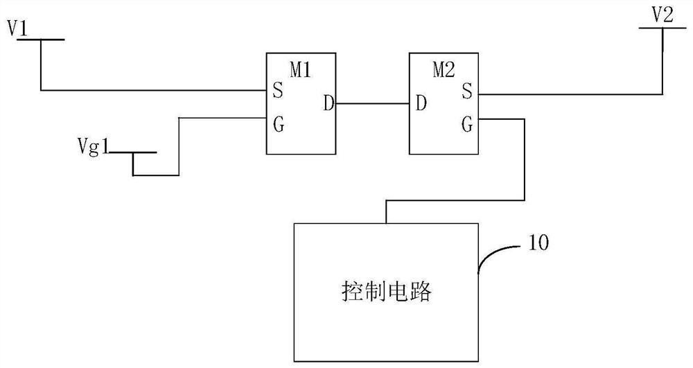
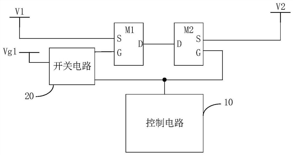
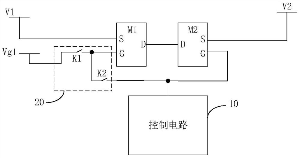
[0070] A charging circuit provided by an embodiment of the present invention. The charging circuit includes a first transistor M1, a second transistor M2 and a control circuit 10; the first pole of the first transistor M1 is connected to the energy storage device V1 of the device to be charged, and the second pole of the first transistor M1 is connected to the second transistor M2. The second pole; the control pole of the second transistor M2 is connected to the control circuit 10, and the first pole of the second transistor M2 is connected to the power supply device V2; t...


PUM


Abstract

The invention relates to a charging circuit, a charging chip, a mobile terminal and a charging system. The charging circuit comprises a first transistor, a second transistor and a control circuit. Thecontrol electrode of the first transistor is connected with a preset voltage end, a first electrode of the first transistor is connected with an energy storage device of equipment to be charged, anda second electrode of the first transistor is connected with a second electrode of the second transistor; the control electrode of the second transistor is connected with the control circuit, and thefirst electrode of the second transistor is connected with power supply equipment; the control circuit is used for controlling the working state of the second transistor; and when the first transistorand / or the second transistor are / is in a cut-off state, the difference value between the voltage of the preset voltage end and the maximum voltage when the energy storage device is fully charged is smaller than a preset threshold value. According to the embodiment of the invention, the electromigration phenomenon in the two transistors when charging is not carried out can be avoided, and the problem that the charging circuit generates heat seriously when charging is carried out is further avoided.

Description

technical field [0001] The present application relates to the technical field of charging, in particular to a charging circuit, a charging chip, a mobile terminal and a charging system. Background technique [0002] With the development of electronic equipment, users have higher and higher requirements for charging technology of electronic equipment. For example, it is necessary to shorten the charging time, reduce the heating phenomenon of charging, and the like. Among them, fast charging has become a development trend of charging technology. [0003] At present, electromigration phenomenon often occurs in the charging circuit used in fast charging, which causes the charging power of the electronic device to increase during charging, which in turn causes the electronic device to heat up seriously. Contents of the invention [0004] Based on this, it is necessary to provide a charging circuit, a charging chip, a mobile terminal and a charging system capable of avoiding e...

Claims


Application Information

Patent Timeline
IPC IPC(8): H02J7/00
CPCH02J7/0029H02J7/0031H02J7/0068H02J2310/22H02J2207/30H02J7/0071H02J7/0034
Inventor 刘绍斌田晨
Owner GUANGDONG OPPO MOBILE TELECOMM CORP LTD
Why Eureka
Try Eureka