
A rear underrun protection device

A protective device and anti-collision bar technology, which is applied to vehicle parts, transportation and packaging, vehicle safety arrangements, etc., can solve the problems of time-consuming, complex automation, difficult manual execution, etc., and achieve low production and maintenance costs, simple design, and strong The effect of the design

Pending Publication Date: 2020-12-22
VBG GRUP PABL
View PDF5 Cites 0 Cited by
  • Summary
  • Abstract
  • Description
  • Claims
  • Application Information

AI Technical Summary

Problems solved by technology

As a result, a rather complex series of movements are required to raise or lower the beam, making the process not only time-consuming and difficult to perform manually, but also complicating automation using motors

Method used


Image

  • A rear underrun protection device
  • A rear underrun protection device
  • A rear underrun protection device

Examples


Embodiment Construction

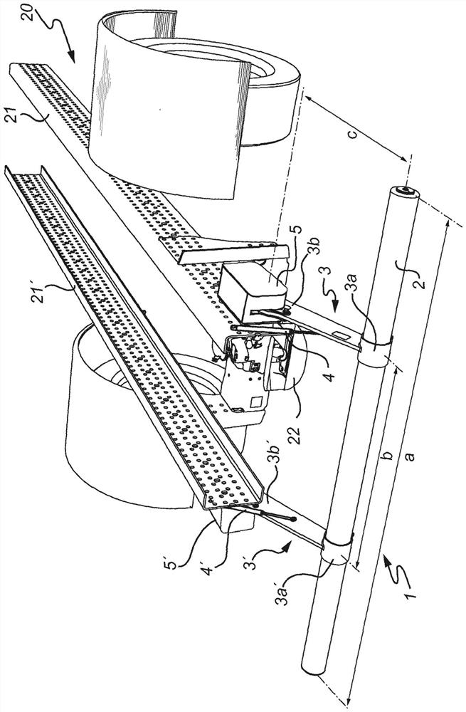
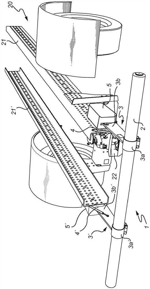
[0042] Figure 1a and Figure 1b The rear underguard 1 is shown mounted to the rear of a towing vehicle 20 . In this case, the towing vehicle 20 is a motorized truck. However, it should be noted that an intermediate trailer, ie a trailer pulled by a motorized truck which in turn pulls the following trailer, is also a towing vehicle in the sense used herein.

[0043]The rear underbody guard 1 includes a crash bar 2, hereafter referred to as "bar" for the sake of brevity. In the example shown, the rod 2 is elongated and straight, and the cross-section of the rod 2 is circular. However, in different examples the rod 2 may be curved and / or have a different cross-section, such as a rectangular cross-section. The pole 2 is arranged to be substantially horizontal when the towing vehicle 20 is standing on level ground. The longitudinal extension of the rod 2 is arranged transversely with respect to the towing vehicle 20 . In other words, the bar 2 is arranged to extend substantia...


PUM


Abstract

A rear underrun protection device (1) for a towing vehicle (20) is disclosed. The rear underrun protection device (1) comprises an impact bar (2), two support arms (3, 3') rotatably connected to the towing vehicle (20), a driver movable in a uniform direction, and a transmission arrangement. The impact bar (2) can be raised, lowered and locked in position by moving the driver in the uniform direction.

Description

technical field [0001] The invention relates to a rear lower protection device for towing vehicles. Background technique [0002] Trucks and other large road vehicles are usually equipped with some type of underguard to prevent smaller vehicles from ending up under the truck in the event of a collision. There are lower guards for frontal, side and rear impacts, an example of the last mentioned type disclosed in WO2017 / 130015. [0003] The rear underguard typically has a cross member attached to the rear of the truck via an arm. The arms may be rotatable, allowing the beam to be raised so that the trailer can be attached to the truck. To raise or lower the beam, the arm is first unlocked, then rotated, and finally locked in the new position. As a result, a rather complex series of movements are required to raise or lower the beam, which not only makes the process time-consuming and difficult to perform manually, but also complicates automating it using motors. [0004] Fr...

Claims


Application Information

Patent Timeline
Patent Type & Authority Applications(China)
IPC IPC(8): B60R19/38B60R19/56
CPCB60R19/38B60R19/56
Inventor 米绍·卡里奥科皮罗宾·詹森
Owner VBG GRUP PABL
Learn More