Plate shearing machine with automatic positioning and clamping functions

An automatic positioning and shearing machine technology, which is applied to shearing equipment, shearing devices, manufacturing tools, etc., can solve the problems of not being able to apply different specifications of plates, fertilizers cannot be cleaned in time, clamping and positioning, etc., to avoid debris scraping No damage, the surface of the board is clean, and the effect of ensuring safety

Active Publication Date: 2020-12-25
临沂仕再新型建筑材料有限公司
View PDF5 Cites 0 Cited by
  • Summary
  • Abstract
  • Description
  • Claims
  • Application Information

AI Technical Summary

Problems solved by technology

[0004] Aiming at the deficiencies of the existing technology, the invention provides a shearing machine with automatic positioning and clamping, which has automatic positioning and clamping of plates, and has multi-level adjustments suitable for plates of different specifications, and automatically cleans up the debris generated after shearing It solves the problem that it cannot be applied to the clamping and positioning of plates of different specifications, and the fertilizer produced by shearing cannot be cleaned up in time.

Method used


Image

  • Plate shearing machine with automatic positioning and clamping functions
  • Plate shearing machine with automatic positioning and clamping functions
  • Plate shearing machine with automatic positioning and clamping functions

Examples


Embodiment Construction

[0023] The technical solutions in the embodiments of the invention will be clearly and completely described below in conjunction with the accompanying drawings in the embodiments of the invention. Obviously, the described embodiments are only part of the embodiments of the invention, not all of them. Based on the embodiments of the invention, all other embodiments obtained by persons of ordinary skill in the art without making creative efforts belong to the protection scope of the invention.

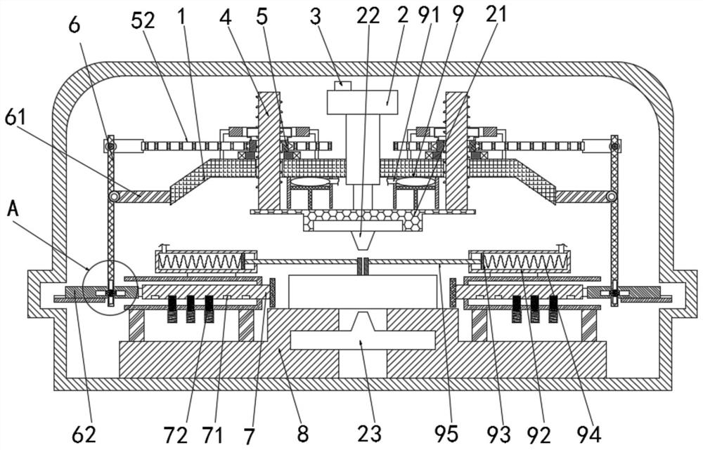
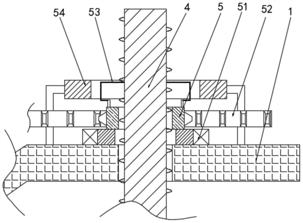
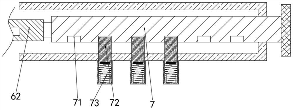
[0024] see Figure 1-4 , a plate shearing machine with automatic positioning and clamping, comprising a fixed frame 1, a driving device 2 is arranged on the upper part of the fixed frame 1, a shearing device 21 is arranged below the driving device 2, and an upper Shearing knife 22, the lower part of upper shearing knife 22 is provided with following shearing knife 23, the top of driving device 2 is provided with switch 3, and the middle of fixed frame 1 is provided with threaded column 4...


PUM


Abstract

The invention relates to the technical field of plate shearing machines, and discloses a plate shearing machine with automatic positioning and clamping functions. The plate shearing machine comprisesa fixed frame; a thread column is provided at the middle of the fixed frame; a thread sleeve is provided on the outer side of the thread column; a tooth rod is provided behind the thread sleeve; a connecting rod is movably connected to the left side of the tooth rod; an ejector rod is movably connected to the upper portion of the connecting rod; a sliding plate is movably connected to the lower end of the connecting rod; a fixed plate is fixedly connected to the right side of the sliding plate; a limiting port is formed in the fixed plate; a limiting block is provided in the limiting port; anda solenoid is provided under the limiting block. According to the plate shearing machine with the automatic positioning and clamping functions, the thread column moves downwards to drive the thread sleeve to rotate, and the thread sleeve drives the tooth rod to move leftwards; an external coil of the solenoid is powered on; the limiting block moves downwards; the sliding plate moves rightwards and is extruded to the left side of a plate to be machined; the limiting block moves into the limiting port under the elastic force of a spring; and the fixed plate is fixed and clamps the plate to be machined, so as to achieve the effect of positioning and clamping the plate before shearing.

Description

technical field [0001] The invention relates to the technical field of shearing machines, in particular to a shearing machine with automatic positioning and clamping. Background technique [0002] The shearing machine is a machine for cutting plates. In the metal processing industry, the shearing machine is widely used. The shearing machine is a kind of forging machinery, which is suitable for various thicknesses of plates. It is very convenient to use. The current market The shearing machine above has the following problems in use: the plate cannot be clamped and positioned before shearing the plate, and it cannot be applied to plates of different specifications; Injure staff. In order to solve the above problems, a shearing machine with automatic positioning and clamping is proposed. Contents of the invention [0003] (1) Solved technical problems [0004] Aiming at the deficiencies of the existing technology, the invention provides a shearing machine with automatic p...

Claims


Application Information

Patent Timeline
Patent Type & Authority Applications(China)
IPC IPC(8): B23D15/06B23D33/00B23D33/02
CPCB23D15/06B23D33/02B23D33/00
Inventor 俞小林
Owner 临沂仕再新型建筑材料有限公司
Why Eureka
Try Eureka