Porcelain plate edge coloring device for ceramic industry
A porcelain plate and side foot technology, which is applied in the field of porcelain plate side foot coloring devices used in the ceramic industry, can solve the problem of inconsistent coloring effects on the side legs of porcelain plates, cannot realize the coloring of the side legs of porcelain plates, and can only take one at a time Porcelain plates and other problems, to save working time, reduce workload, reduce production costs
- Summary
- Abstract
- Description
- Claims
- Application Information
AI Technical Summary
Problems solved by technology
Method used
Image
Examples
Embodiment 1
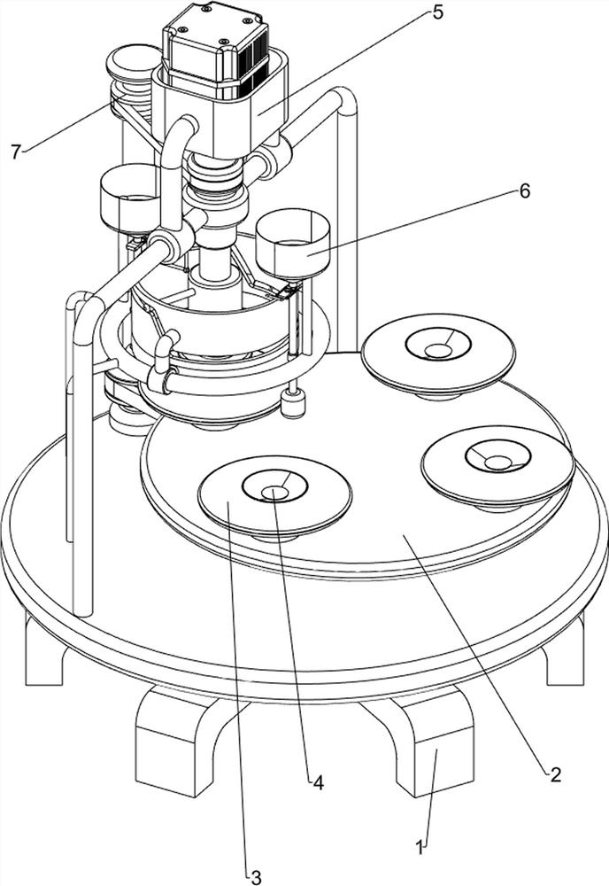
[0024] A device for coloring the sides of porcelain plates used in the ceramic industry, such as figure 1 , figure 2 , image 3 , Figure 4 , Figure 5 As shown, it includes base 1, rotating tray 2, rotating disk 3, suction cup 4, rotating mechanism 5 and paint adding mechanism 6, the rotating type is provided with rotating tray 2 on the base 1, and the uniform rotating type is provided with rotating tray 2. The disc 3 and the rotating disc 3 are provided with a sucker 4, the left side of the base 1 is provided with a rotating mechanism 5, and the rotating mechanism 5 is provided with a paint adding mechanism 6.
[0025] When people paint the edge of the porcelain plate, they usually manually hold the plate for coloring, and cannot automatically color the edge of the porcelain plate. Therefore, people can use this equipment to first place the porcelain plate that needs to be colored on the rotating On the disk 3, the suction cup 4 will hold and fix the porcelain disk, and...
Embodiment 2
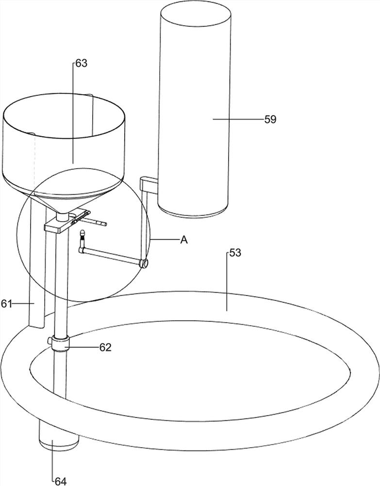
[0027] On the basis of Example 1, such as figure 1 , figure 2 , image 3 , Figure 4 , Figure 5 As shown, the rotating mechanism 5 includes an L bar 51, a support bar 52, a mounting ring 53, a first bracket 54, a first bump 55, a second bump 56, a mounting frame 57, a motor 58, a rotating sleeve 59, a sleeve Rod 510, long rod 511, first spring 512 and telescopic rod 513, the left side on the base 1 is provided with L bar 51 symmetrically front and back, and the top of L bar 51 is provided with installation frame 57, and motor 58 is installed on the installation frame 57, and motor 58 The output shaft of the rotary sleeve 59 is provided with a rotating sleeve 59, and the sliding type in the rotating sleeve 59 is provided with a sleeve rod 510. The lower side of the sleeve rod 510 is provided with a long rod 511. There is a first spring 512, the top of the first spring 512 is connected with the long rod 511, and the left side of the base 1 is evenly provided with three sup...
Embodiment 3
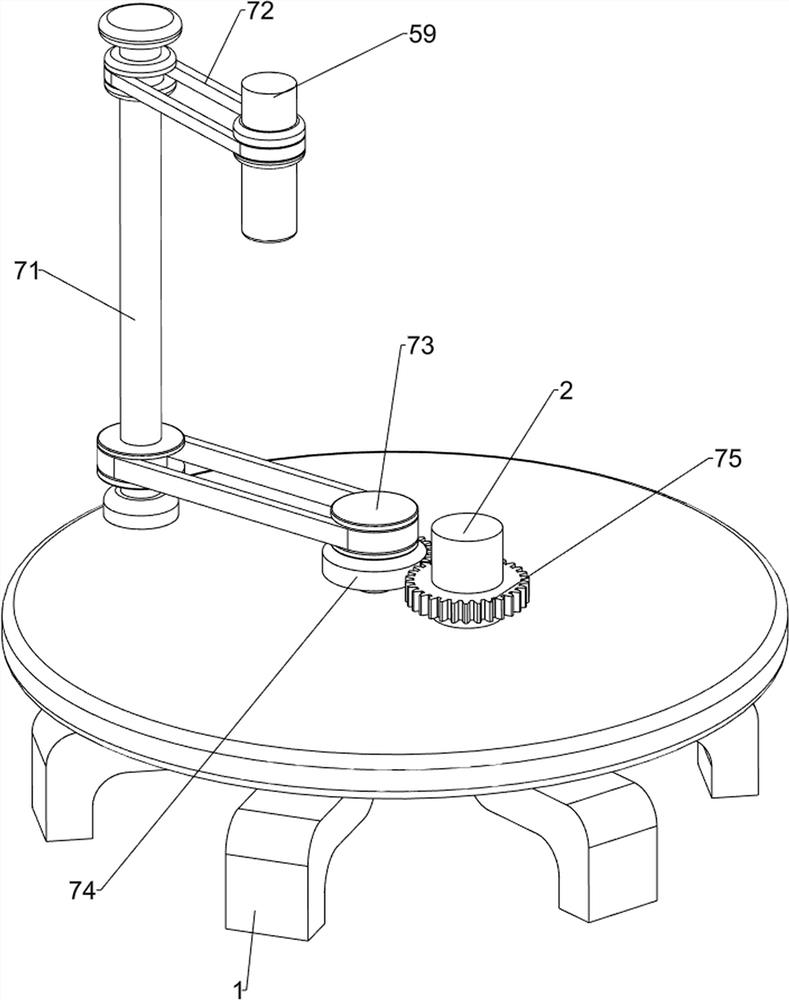
[0032] On the basis of Example 2, such as figure 1 and Figure 6 As shown, a rotating mechanism 7 is also included, and the left side rotation type is provided with a rotating mechanism 7 on the base 1, and the rotating mechanism 7 includes a rotating column 71, a first transmission assembly 72, a second transmission assembly 73, a half gear 74 and a spur gear 75, the left side rotation type on the base 1 is provided with a rotation column 71, and the middle rotation type on the base 1 is provided with a half gear 74, and a second transmission assembly 73 is wound between the half gear 74 and the rotation column 71, and the rotation column 71 and the rotation sleeve A first transmission assembly 72 is wound between 59, and a spur gear 75 is provided on the lower side of the rotary tray 2, and the spur gear 75 meshes with the half gear 74.
[0033] When the rotating sleeve 59 rotates, the rotation of the rotating column 71 will be driven by the first transmission assembly 72, ...
PUM
 Abstract
Description
Claims
Application Information
 - R&D
- Intellectual Property
- Life Sciences
- Materials
- Tech Scout
- Unparalleled Data Quality
- Higher Quality Content
- 60% Fewer Hallucinations
Browse by: Latest US Patents, China's latest patents, Technical Efficacy Thesaurus, Application Domain, Technology Topic, Popular Technical Reports.
© 2025 PatSnap. All rights reserved.Legal|Privacy policy|Modern Slavery Act Transparency Statement|Sitemap|About US| Contact US: help@patsnap.com


