Building prefabricated slab mixing and solidifying equipment for new materials

A technology of prefabricated panels and new materials, applied in auxiliary forming equipment, manufacturing tools, mold fixing devices, etc., can solve the problems of inconvenient operation and single function, and achieve the effect of easy picking and placing

Pending Publication Date: 2020-12-25
广州好未来科技研究有限公司
View PDF9 Cites 6 Cited by
  • Summary
  • Abstract
  • Description
  • Claims
  • Application Information

AI Technical Summary

Problems solved by technology

[0004] In order to overcome the shortcomings of relatively single function and inconvenient operation in the prior art, the technical problem of the present invention i

Method used


Image

  • Building prefabricated slab mixing and solidifying equipment for new materials
  • Building prefabricated slab mixing and solidifying equipment for new materials
  • Building prefabricated slab mixing and solidifying equipment for new materials

Examples


Embodiment 1

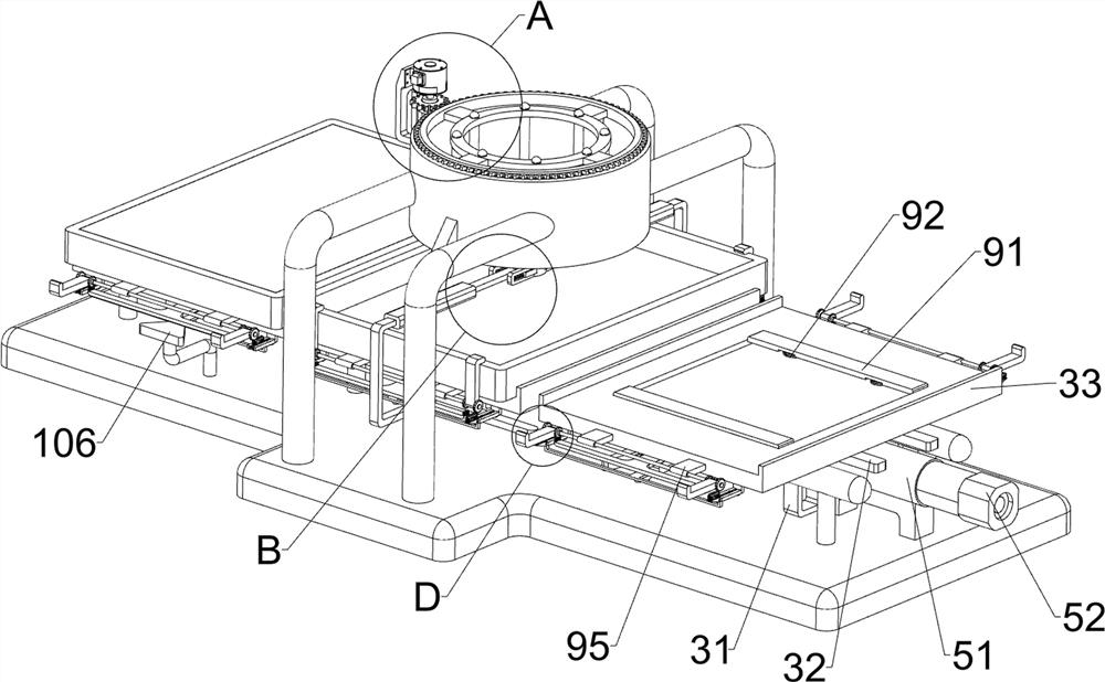
[0029] A kind of mixing solidification equipment for building prefabricated panels for new materials, such as figure 1 , figure 2 and Image 6 As shown, it includes a base plate 1, a support frame 2, a supporting plate mechanism 3, a mold 4 and a propulsion mechanism 5, a support frame 2 is symmetrically arranged on the base plate 1, and a supporting plate mechanism 3 is slidingly connected between the supporting frames 2, and the supporting plate A mold 4 is placed on the mechanism 3 , and a propulsion mechanism 5 is arranged on the bottom plate 1 .

[0030] When people need to use this equipment, first people place the mold 4 in the pallet mechanism 3, then pour the material for making the prefabricated plate into the mold 4, and then people can start the propulsion mechanism 5, and the propulsion mechanism 5 operates to drive the pallet The plate mechanism 3 moves to the right, and the supporting plate mechanism 3 drives the mold 4 to move to the right, and then when the...

Embodiment 2

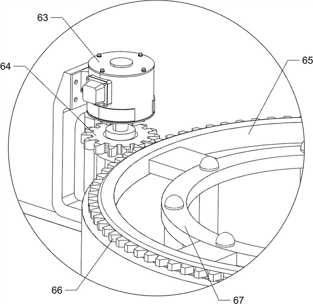
[0035] On the basis of Example 1, such as figure 1 , figure 2 , image 3 , Figure 4 , Figure 5 , Image 6 and Figure 7 As shown, it also includes a stirring mechanism 6, and the stirring mechanism 6 includes a second fixed frame 61, a mixing bucket 62, a servo motor 63, a spur gear 64, a slip ring 65, a rack ring 66 and a stirring frame 67, and the bottom plate 1 is provided with There are a plurality of second fixed mounts 61, a mixing bucket 62 is arranged between the second fixing brackets 61, a servo motor 63 is arranged on the right side of the mixing bucket 62, and a spur gear 64 is arranged on the output shaft of the servo motor 63, and the mixing bucket 62 is rotatably connected with a sliding ring 65, the outer side of the sliding ring 65 is provided with a rack ring 66, the rack ring 66 meshes with the spur gear 64, and the inner side of the sliding ring 65 is provided with a stirring frame 67.

[0036]First, people pour the materials required for making pr...


PUM


Abstract

The invention relates to solidifying equipment, in particular to building prefabricated slab mixing and solidifying equipment for new materials. The building prefabricated slab mixing and solidifyingequipment for the new materials is provided and is diverse in function, easy to operate and high in production efficiency. The building prefabricated slab mixing and solidifying equipment for the newmaterials comprises a bottom plate, wherein supporting frames are symmetrically arranged on the bottom plate; a plate supporting mechanism connected to the supporting frames in a sliding mode, whereina mold is placed on the plate supporting mechanism; and a pushing mechanism arranged on the bottom plate. According to the building prefabricated slab mixing and solidifying equipment for the new materials, the mold is placed through the plate supporting mechanism, and then the mold is conveyed rightwards under cooperation of the pushing mechanism; and through the arrangement of a stirring mechanism, uniform mixing of prefabricated slab materials is achieved.

Description

technical field [0001] The invention relates to a solidification device, in particular to a mixing and solidification device for building prefabricated boards for new materials. Background technique [0002] Prefabricated panels refer to the modules or panels to be used in the project. Because the prefabricated concrete parts are produced and processed in the prefabricated field and are directly transported to the construction site for installation, they are called prefabricated panels. When making prefabricated panels, people usually do it manually. The mold is poured, and then the prefabricated board is formed, and then the mold is removed. Such a long-term manual operation is prone to fatigue, which in turn affects the production efficiency. However, the existing devices usually have a single function, and most of them can only perform one operation. , so that people need to operate between different devices, so it is more troublesome. [0003] Therefore, we need to deve...

Claims


Application Information

Patent Timeline
IPC IPC(8): B28B13/02B28B1/14B28B7/00B28B17/00
CPCB28B1/14B28B7/0014B28B7/0032B28B13/0235B28B17/00
Inventor 黎昔群
Owner 广州好未来科技研究有限公司
Why Eureka
Try Eureka