
Ecological stone demolding equipment for building

A technology for ecological stone and construction, applied in the direction of unloading device, manufacturing tools, etc., can solve the problems of long time and energy, cumbersome and other problems, and achieve the effect of easy demoulding work and simple operation.

Inactive Publication Date: 2020-12-25
傅海冬
View PDF5 Cites 1 Cited by
  • Summary
  • Abstract
  • Description
  • Claims
  • Application Information

AI Technical Summary

Problems solved by technology

[0005] In order to overcome the cumbersome operation of manually taking out the ecological stone from the formwork, the present invention takes a lot of time and effort, and the technical problem to be solved by the present invention is to provide a building ecological Stone demoulding equipment

Method used


Image

  • Ecological stone demolding equipment for building
  • Ecological stone demolding equipment for building
  • Ecological stone demolding equipment for building

Examples


Embodiment 1

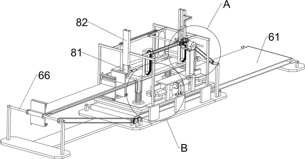
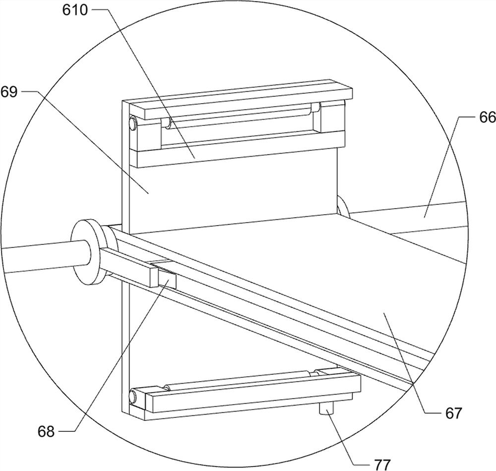
[0025] A kind of ecological stone demoulding equipment for building, such as Figure 1-8 As shown, it includes a base 1, a mounting frame 2, a demoulding mechanism 5 and a moving mechanism 6, the top of the base 1 is connected with a mounting frame 2, the mounting frame 2 is equipped with a demoulding mechanism 5, and the base 1 is equipped with a moving mechanism 6 , the moving mechanism 6 is connected with the demoulding mechanism 5 in transmission.

[0026] The stripping mechanism 5 includes a servo motor 51, a double-sided bevel gear 52, a first bevel gear 53, a first connecting shaft 54, a first transmission belt set 55, a second connecting shaft 56, a second transmission belt set 57, a first Gear 58, sliding lifting frame 59, ring rack 510, connecting frame 511, hollow frame 512, sliding rod 513, support spring 514, suction cup 515, first baffle plate 516, second baffle plate 517, first fixed ring sleeve 518 , fixed seat 519, movable limit plate 520, torsion spring 521,...

Embodiment 2

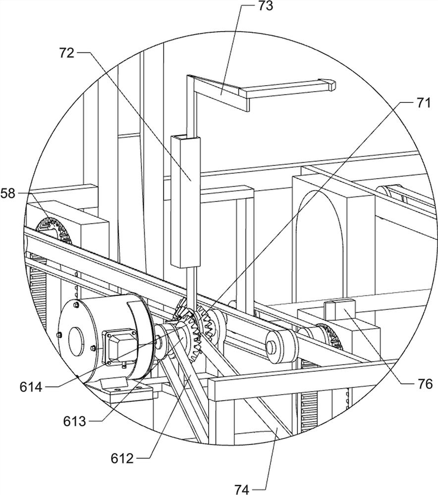
[0030] On the basis of Example 1, such as figure 1 , image 3 , Figure 6 and Figure 8 As shown, it also includes a power automatic switching mechanism 7, and the power automatic switching mechanism 7 includes a sliding collar 71, a fixed guide frame 72, a first push rod frame 73, a second push rod frame 74, a third fixed collar 75, Jack block 76 and ejector rod 77, the outer wall of double-sided bevel gear 52 is connected with sliding collar 71, and the front side of the top of installation frame 2 is connected with fixed guide frame 72, and the fixed guide frame 72 is slidingly connected with first push rod frame 73, The bottom of the first push rod frame 73 is connected with the top of the sliding collar 71, the right side of the sliding collar 71 is connected with the second push rod frame 74, the right side of the right rail frame 82 is connected with the third fixed collar 75, the second push The rod frame 74 is slidably connected in the third fixed collar 75, and th...

Embodiment 3

[0033] On the basis of Example 2, such as Figure 1-2 As shown, a reinforcement structure 8 is also included. The reinforcement structure 8 includes a slide block 81 and a guide rail frame 82. The left and right sides of the upper part of the installation frame 2 are connected with a guide rail frame 82, and the guide rail frame 82 is slidably connected with a slide block 81. The bottom of the slider 81 is connected to the top of the connecting frame 511 .

[0034] The connecting frame 511 can be guided by the guide rail frame 82 and the sliding block 81 to prevent the connecting frame 511 from shaking left and right when moving up and down, thereby facilitating demoulding.


PUM


Abstract

The invention relates to demolding equipment, in particular to ecological stone demolding equipment for a building. The ecological stone demolding equipment for the building provided by the inventionis easy to operate and capable of saving time and labor. The ecological stone demolding equipment for the building comprises a base, and a mounting rack is connected to the middle part of the base; ademolding mechanism mounted on the mounting rack; and a moving mechanism mounted on the base, and the moving mechanism is in transmission connection with the demolding mechanism. According to the ecological stone demolding equipment for the building provided by the invention, a mold with ecological stone can be conveyed leftwards through the moving mechanism, demolding can be conducted on the ecological stone through the demolding mechanism, the ecological stone is moved out of the mold, the moving mechanism and the demolding mechanism can automatically switch power to work through an automatic power switching mechanism, and guiding can be conducted through a reinforcing structure; and demolding work is facilitated, and therefore, the ecological stone does not need to be manually taken outof the mold, time and labor can be saved, and the operation is simple.

Description

technical field [0001] The invention relates to a demoulding device, in particular to an ecological stone demoulding device for building. Background technique [0002] Eco-stone is made of recyclable materials that do not need to be mined, and has better load-bearing capacity. 85% of the main raw materials for making eco-stone are by-products of industrial production, such as fly ash, slag, cement kiln dust and fillers, etc. The manufacturing process of ecological stone is that the material is first mixed with water to produce a chemical reaction, and finally the resulting clay-like substance is poured into the formwork for solidification to make bricks. After the ecological stone is cured, it needs to be demoulded, and the ecological stone is taken out of the formwork At present, the ecological stone is generally taken out of the template manually, which is cumbersome and requires a lot of time and energy. [0003] Therefore urgently need to research and develop a kind of ...

Claims


Application Information

Patent Timeline
IPC IPC(8): B28B13/06
CPCB28B13/06
Inventor 傅海冬
Owner 傅海冬
Learn More