
High-precision aluminum profile bending mechanism

A bending mechanism and aluminum profile technology, which is applied to metal processing equipment, feeding devices, positioning devices, etc., can solve the problems of reducing the service life of the bending mechanism, affecting the bending accuracy, and easily damaging the aluminum profiles, so as to improve the transmission Stability and transmission accuracy, easy demoulding work, and the effect of improving bending quality

Pending Publication Date: 2021-05-04
张家港市和力机械制造有限公司
View PDF0 Cites 0 Cited by
  • Summary
  • Abstract
  • Description
  • Claims
  • Application Information

AI Technical Summary

Problems solved by technology

The above-mentioned bending mechanism has the following disadvantages: 1. During the bending process, there is a large friction force between the chain and the first and second sprockets, and the sprockets are easy to wear the chain, which easily increases the pitch of the chain , so that it is easy to be out of touch with the sprocket and affect the bending accuracy, and even the chain may break, which is not only prone to production accidents, but also greatly reduces the service life of the bending mechanism; 2. After the bending is completed , the aluminum profile will be tightly stuck in the wheel groove of the wheel mold, and the demoulding work cannot be performed well, and the aluminum profile is easily damaged during the forced demoulding process; 3. The wheel groove of the wheel mold and the groove of the sliding formwork Only the upper and lower ends of the aluminum profile can be clamped, the ribs on the inner wall of the aluminum profile cannot be clamped, and the ribs on the inner wall are prone to warping during the bending process

Method used


Image

  • High-precision aluminum profile bending mechanism
  • High-precision aluminum profile bending mechanism
  • High-precision aluminum profile bending mechanism

Examples


Embodiment Construction

[0017] The technical solutions of the present invention will be further described below in conjunction with the accompanying drawings and preferred embodiments.

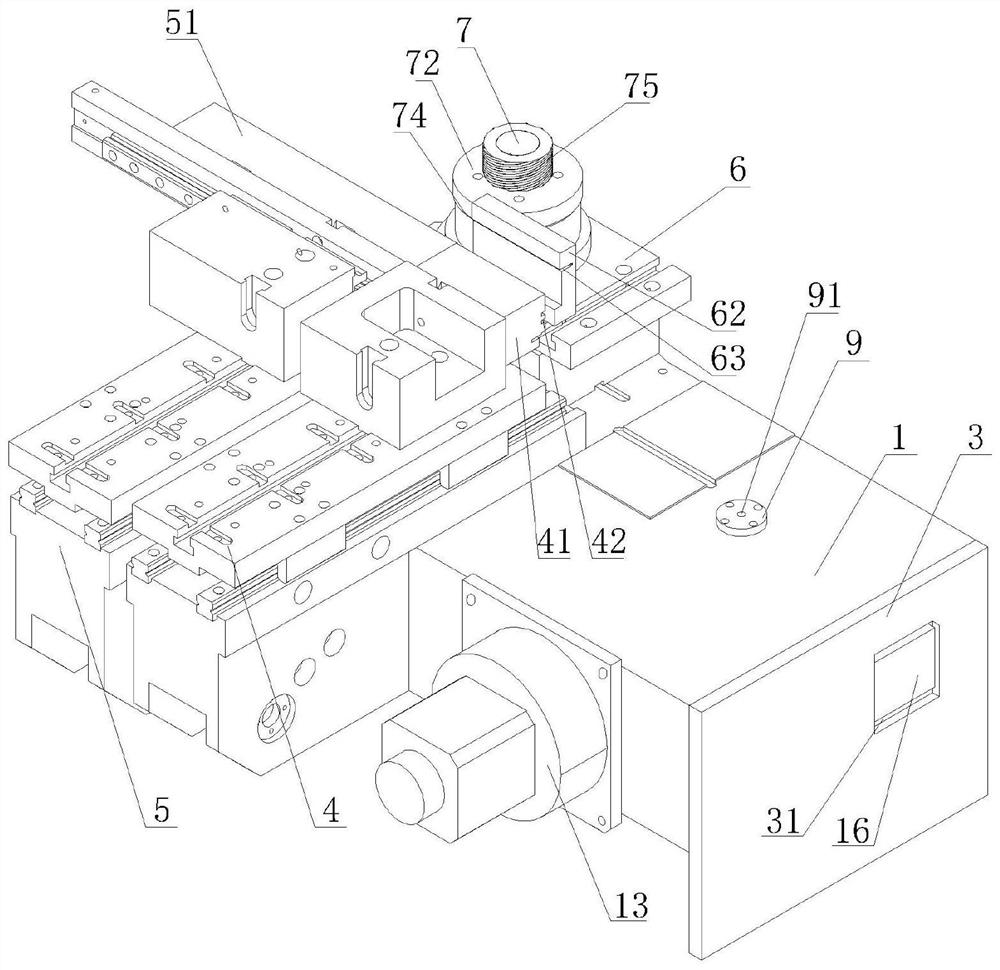
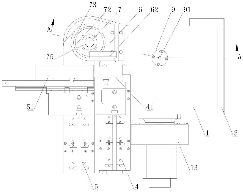
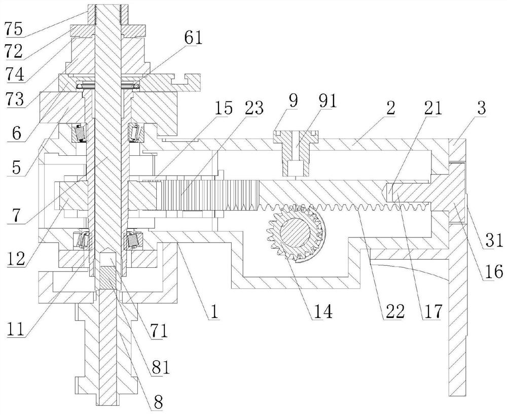
[0018] Such as figure 1 , figure 2 , image 3 As shown, the high-precision aluminum profile bending mechanism described in the present invention includes: a frame 1, on which a main shaft tube 11 capable of rotating in the frame 1 is arranged, and the lower end of the main shaft tube 11 is keyed to a The first gear 12 is provided with a servo motor 13 on the frame 1 on the right side of the main shaft tube 12, and the output shaft of the servo motor 13 is keyed with a second gear 14, and is positioned on the frame 1 above the second gear 14. A rack plate 2 is provided for sliding in the middle, and the connection structure between the rack plate 2 and the frame 1 is as follows: a chute cavity 15 is provided at the left end of the frame 1, and the left end of the rack plate 2 extends into the chute cavity 15 and c...


PUM

PropertyMeasurementUnit
lengthaaaaaaaaaa

Abstract

The invention discloses a high-precision aluminum profile bending mechanism which comprises a rack, a main shaft tube arranged on the rack, a first gear arranged on the main shaft tube, a servo motor arranged on the rack, a second gear connected to the servo motor and a rack plate slidably arranged in the rack, wherein a first rack meshed with the second gear is arranged at the bottom of the rack plate, and a second rack meshed with the first gear is arranged at the left end of the rack plate; a sliding plate die is arranged on the outer side of the rack; and a mounting seat is arranged on the rack, a bearing is arranged in the mounting seat, the main shaft tube is in close fit to the bearing, a rotating shaft is arranged in the main shaft tube in a penetrating manner, the lower end of the rotating shaft is connected to a lifting mechanism, a wheel die group consisting of a plurality of mutually independent wheel dies is sleeved at the upper end of the rotating shaft, and a pressing and blocking mechanism is arranged at the top of the rotating shaft. The high-precision aluminum profile bending mechanism has the advantages that the service life is prolonged, aluminum profile demolding is facilitated, and the bending precision and the bending quality of the aluminum profile are greatly improved.

Description

technical field [0001] The invention relates to a high-precision aluminum profile bending mechanism. Background technique [0002] The bending mechanism in the aluminum profile bending machine includes: a frame, a main shaft is arranged on the frame, a wheel mold is arranged on the main shaft, and a wheel groove capable of accommodating the inner wall of the aluminum profile is arranged on the wheel mold. A pipe bending arm connected to the main shaft is provided on the outer side of the pipe bending arm. A sliding plate mold aligned with the wheel mold is provided on the pipe bending arm. A groove capable of accommodating the outer wall of the aluminum profile is provided on the sliding plate mold. A first wheel is provided on the main shaft. The sprocket is provided with a reducer on the frame, and a second sprocket is arranged on the reducer. The first sprocket and the second sprocket are connected by a chain, and the reducer can drive the second sprocket to rotate throug...

Claims


Application Information

Patent Timeline
Patent Type & Authority Applications(China)
IPC IPC(8): B21D7/00B21D7/16B21D43/00
CPCB21D7/00B21D7/16B21D43/003
Inventor 黄永平刘昌松徐志芬
Owner 张家港市和力机械制造有限公司
Learn More