A synchronous display signal light gun and portable lighting communication equipment

A technology of synchronous display and communication equipment, applied in the field of aviation communication, can solve the problems of unknown, single form, poor command ability and so on

Active Publication Date: 2022-07-15
成都伯航科技有限公司
View PDF0 Cites 0 Cited by
  • Summary
  • Abstract
  • Description
  • Claims
  • Application Information

AI Technical Summary

Problems solved by technology

[0003] However, most of the existing navigation aids are fixed on the airport, and the form is relatively simple. It is impossible to conduct information interaction through complex commands such as Morse code to command the aircraft. When emitting light signals to the aircraft, it is necessary to make the light signals face the aircraft so that The aircraft can accurately receive the light signal, but the light signal sent by the existing fixed navigation light cannot adjust the direction according to the position of the aircraft, the aircraft may not be able to receive the light phenomenon, and its command ability is poor; Lights are time-consuming, labor-intensive, and have poor maneuverability, especially in the military field, and cannot be used as a supplement when radio communication fails
[0004] In addition, because the light beam is emitted forward, and in order to ensure sufficient visual distance, the light intensity is usually strong, and it is not easy for the staff who operate the light emission to grasp the emitted light signal, and it is impossible to know if the emitted light signal is wrong.

Method used


Image

  • A synchronous display signal light gun and portable lighting communication equipment
  • A synchronous display signal light gun and portable lighting communication equipment
  • A synchronous display signal light gun and portable lighting communication equipment

Examples


Embodiment Construction

[0038] In order to make the objectives, technical solutions and advantages of the present invention clearer, the present invention will be further described in detail below with reference to the accompanying drawings.

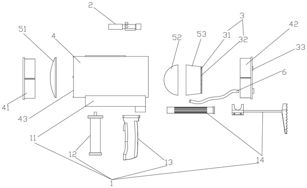
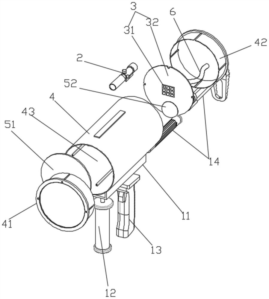
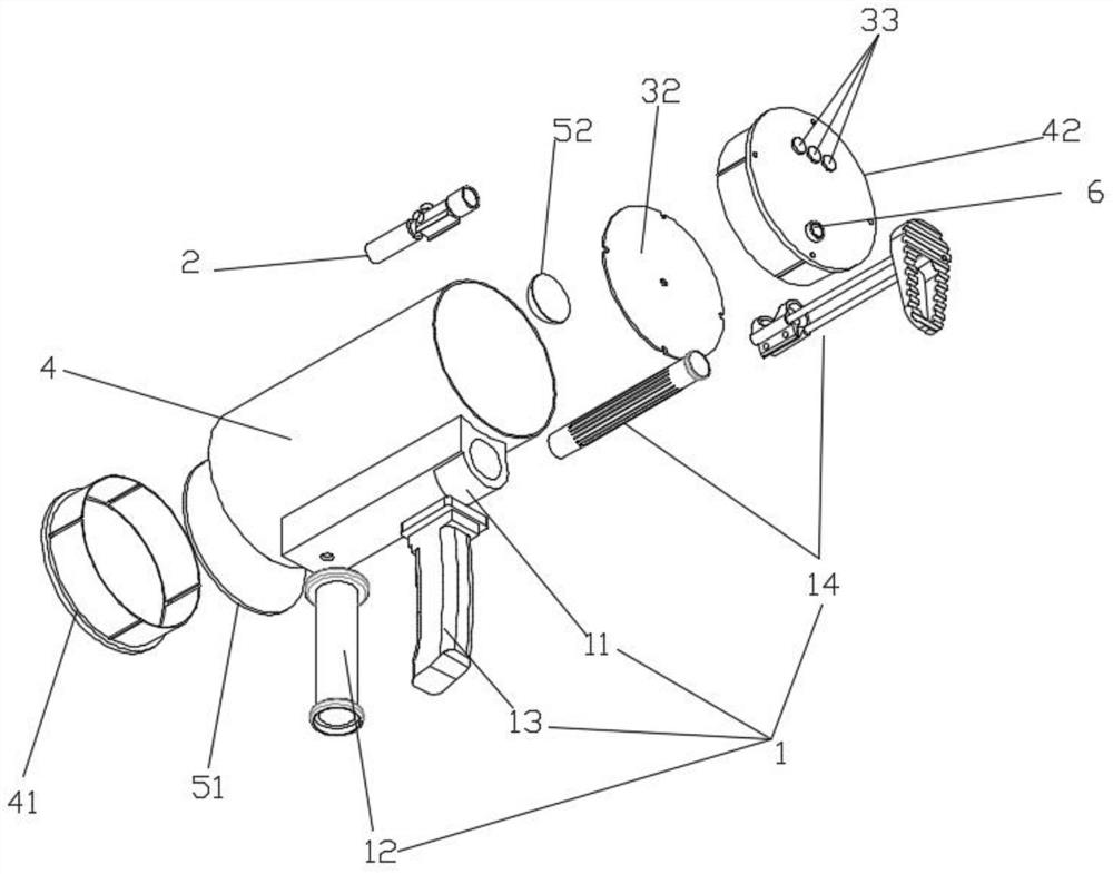
[0039] like Figure 1-Figure 4 As shown in the figure, the embodiment of the synchronous display signal light gun disclosed in the present invention includes a gun base 1, an sight 2, a signal light emission component and a synchronous display module. The signal light emission component is arranged on the gun seat 1, and the sight 2 is arranged on the On the signal light emission component, the light signal emission direction of the signal light emission component is the same as the aiming direction of the sight 2. The sight 2 is used to aim the aircraft and make the signal light emission component emit light signals towards the aircraft. The synchronous display module is arranged on the gun seat. 1 or the visible position of the signal light emitting component...


PUM


Abstract

The invention discloses a synchronous display signal light gun, comprising a gun seat, sights, a signal light emitting component and a synchronous display module. The signal light emitting component is arranged on the gun seat, the sight is arranged on the signal light emitting component, and the signal light emits The light signal emission direction of the component is the same as the aiming direction of the sight. The synchronous display module is arranged in the visible position of the gun seat or the signal light emission component. The synchronization display module is used to receive and synchronously display the light signal emitted by the signal light emission component. The invention also discloses a portable lighting communication device comprising the above-mentioned synchronous display signal light gun. The synchronous display signal light gun and the portable light communication equipment provided by the present invention are convenient for transmitting light signals to the aircraft, ensure the transmission of the light signals, have strong maneuverability, are beneficial to effectively guide the aircraft in various environments such as radio communication failure, and are easy to operate. The personnel shall know whether the light signal emitted is correct, so as to ensure the correct transmission of the signal.

Description

technical field [0001] The invention relates to the field of aviation communication, in particular to a synchronous display signal light gun and a portable lighting communication device. Background technique [0002] In order to ensure the safety of navigation, it is necessary to establish communication between the aircraft and the ground to guide the aircraft. At present, radio communication is often used between the ground and the aircraft, but the radio is easy to be interfered and captured. When radio silence is required, and the aircraft or ground communication equipment is damaged, the aircraft can only be guided by the fixed navigation lights on the airport. [0003] However, the existing navigation aids are mostly fixed on the airport, and the form is relatively simple, and it is impossible to exchange information through complex commands such as Morse code to command the aircraft. The aircraft can accurately receive the light signal, and the light signal sent by th...

Claims


Application Information

Patent Timeline
Patent Type & Authority Patents(China)
IPC IPC(8): B64F1/18F21V5/04F21V9/40F21V13/02F21V13/04F21V15/00F21V19/00F21W111/00
CPCB64F1/18F21V5/04F21V13/02F21V19/00F21V9/40F21V13/045F21V15/00F21W2111/00
Inventor 林治文杨晨
Owner 成都伯航科技有限公司
Why Eureka
Try Eureka