
A building prefabricated light steel structure wall

A light-weight steel and wall technology, applied in building components, building structures, buildings, etc., can solve the problems of panel replacement, waste, and low wall installation efficiency, and achieve high installation efficiency, reduce use costs, and save resource effect

Active Publication Date: 2021-10-01
广东谦元建设有限公司
View PDF10 Cites 0 Cited by
  • Summary
  • Abstract
  • Description
  • Claims
  • Application Information

AI Technical Summary

Problems solved by technology

[0005] Aiming at the deficiencies of the prior art, the present invention provides a prefabricated lightweight steel structure wall, which ensures that the steel structure wall can be replaced with its installed board during use, so that the long-term poor damage of the board can be repaired in time. Replacement ensures that the steel structure wall can be used normally, and at the same time avoids the need to replace the steel structure wall after the plate is damaged, saving resources and reducing the cost of use, making the steel structure wall relatively traditional steel structure The installation efficiency of the wall is higher, and the steel structure wall can be installed quickly, etc., which solves the problem that the current steel structure wall cannot replace the board installed in the steel structure, and the board is damaged during long-term use After that, it needs to be replaced together with the steel structure wall, which causes waste and affects the normal use of the steel structure wall, and the installation efficiency of the traditional steel structure wall is relatively low during the installation process, and the steel structure wall cannot be quickly replaced. problem with installation

Method used


Image

  • A building prefabricated light steel structure wall
  • A building prefabricated light steel structure wall
  • A building prefabricated light steel structure wall

Examples


Embodiment Construction

[0027] The following will clearly and completely describe the technical solutions in the embodiments of the present invention with reference to the accompanying drawings in the embodiments of the present invention. Obviously, the described embodiments are only some of the embodiments of the present invention, not all of them. Based on the embodiments of the present invention, all other embodiments obtained by persons of ordinary skill in the art without making creative efforts belong to the protection scope of the present invention.

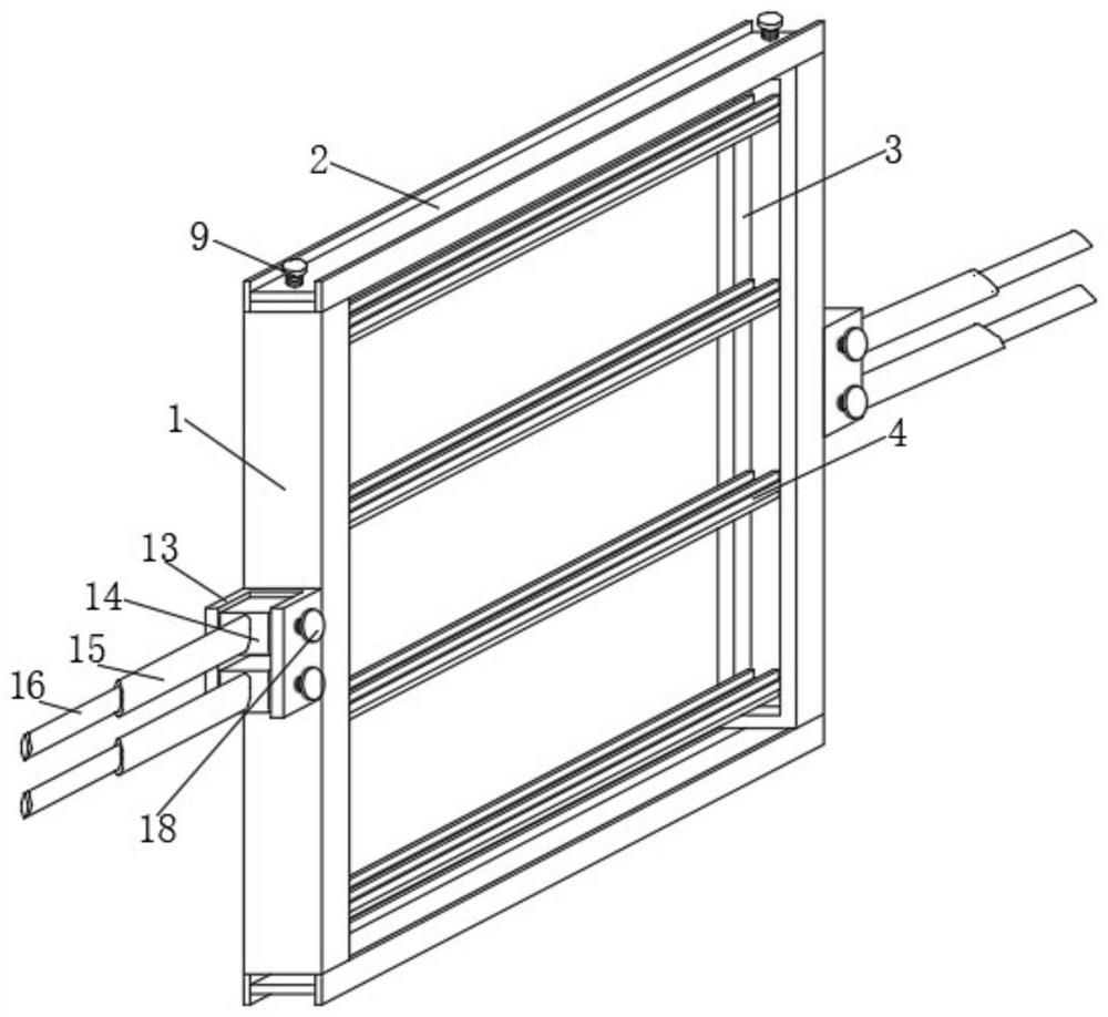
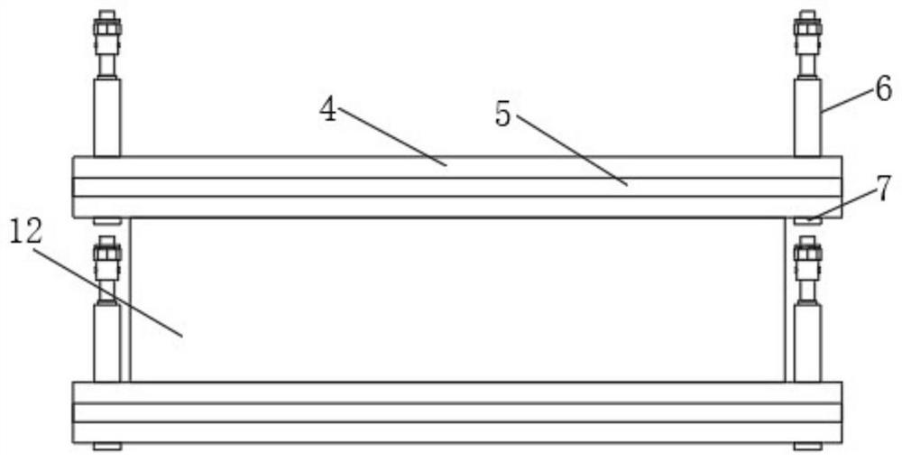
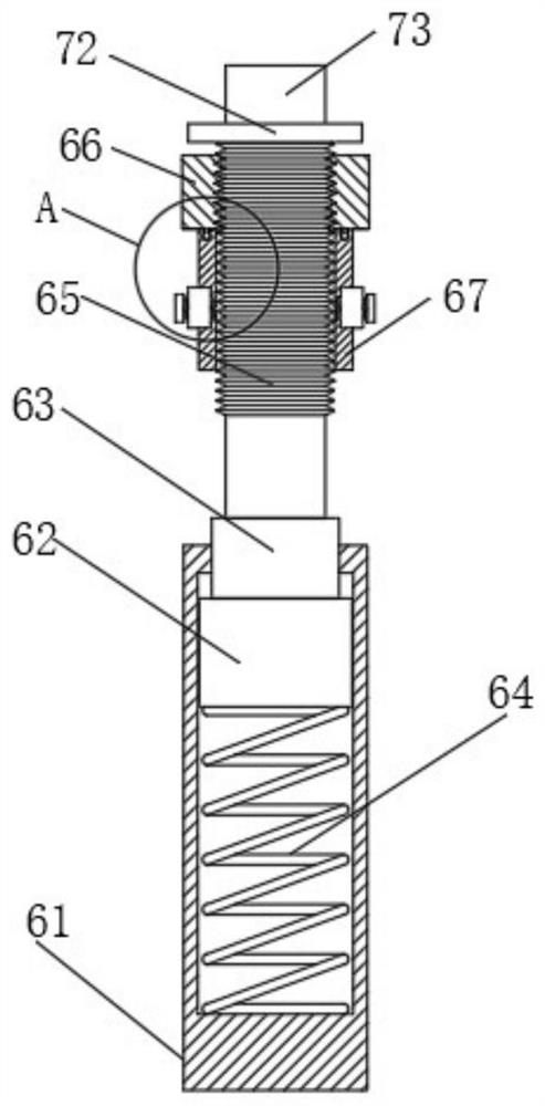
[0028] see Figure 1-6 , a building prefabricated light steel structure wall, including a wall frame 1, the top and bottom of the wall frame 1 are fixedly connected with I-beams 2, and the corresponding inner sides of the wall frame 1 are provided with sliding grooves 3, Several sliding frame bodies 4 are slidably connected in the sliding groove 3, and a positioning support mechanism 6 is fixedly installed on both sides of the top of the sliding ...


PUM


Abstract

The invention relates to the technical field of building walls, and discloses a building prefabricated light steel structure wall, including a wall frame, the top and bottom ends of the wall frame are fixedly connected with I-beams, and the corresponding inner side of the wall frame is Sliding grooves are provided, and several sliding frame bodies are slidably connected in the sliding grooves. Positioning support mechanisms are fixedly installed on both sides of the top of the sliding frame body. The positioning support mechanism includes a fixed cylinder, a connecting column, a threaded column and a positioning column. The connecting post is slidably connected in the fixing cylinder, the threaded post is fixedly connected to the top middle of the connecting post, and the positioning post is fixedly connected to the top middle of the threaded post. The prefabricated light-weight steel structure wall of the building ensures that the steel structure wall can be replaced with its installed board during use, so that the board can be replaced in time for long-term poor damage, ensuring that the steel structure wall can be used normally. The use cost is reduced, and the installation efficiency of the steel structure wall is higher than that of the traditional steel structure wall.

Description

technical field [0001] The invention relates to the technical field of building walls, in particular to a building prefabricated light steel structure wall. Background technique [0002] Steel structure is a structure composed of steel materials, which is one of the main types of building structures. The structure is mainly composed of steel beams, steel columns, steel trusses and other components made of section steel and steel plates, and adopts rust removal and antirust processes such as silanization, pure manganese phosphating, washing and drying, and galvanizing. The components or components are usually connected by welds, bolts or rivets. Because of its light weight and easy construction, it is widely used in large factories, stadiums, super high-rises and other fields. Steel structures are prone to corrosion. Generally, steel structures need to be derusted, galvanized or painted, and they need to be maintained regularly. [0003] The walls of light steel structure ...

Claims


Application Information

Patent Timeline
Patent Type & Authority Patents(China)
IPC IPC(8): E04B2/74E04B2/76E04B2/82E04C2/38E04C2/40
CPCE04B2/7407E04B2/76E04B2/827E04B2002/7477E04C2/384E04C2/40
Inventor 朱爱国
Owner 广东谦元建设有限公司
Learn More