Adjustable impeller structure and hydroelectric equipment

An adjustable technology for power generation equipment, applied in hydroelectric power generation, mechanical equipment, reaction engines, etc., can solve problems such as inability to achieve angle adjustment, failure to meet use requirements, and use range limitations, and achieve novel design, strong practicability, and Wide range of effects

Active Publication Date: 2020-12-25
湖南新邵筱溪水电开发有限责任公司
View PDF10 Cites 1 Cited by
  • Summary
  • Abstract
  • Description
  • Claims
  • Application Information

AI Technical Summary

Problems solved by technology

[0004] The impeller mechanism is used in hydroelectric power generation equipment, but the existing impeller and hub are in an integrated state, or are directly welded and fixed, and the angle adjustment cannot be realized. The scope of use is limited and cannot meet different use requirements.

Method used


Image

  • Adjustable impeller structure and hydroelectric equipment
  • Adjustable impeller structure and hydroelectric equipment
  • Adjustable impeller structure and hydroelectric equipment

Examples


Embodiment Construction

[0024]The technical solutions in the embodiments of the present invention will be clearly and completely described below in conjunction with the accompanying drawings in the embodiments of the present invention. Obviously, the described embodiments are only a part of the embodiments of the present invention, rather than all the embodiments. Based on the embodiments of the present invention, all other embodiments obtained by those of ordinary skill in the art without creative work shall fall within the protection scope of the present invention.

[0025]In addition, the element in the present invention is referred to as being "fixed to" or "disposed on" another element, and it may be directly on the other element or a central element may also be present. When an element is considered to be "connected" to another element, it can be directly connected to the other element or an intermediate element may be present at the same time. The terms "vertical", "horizontal", "left", "right" and sim...


PUM


Abstract

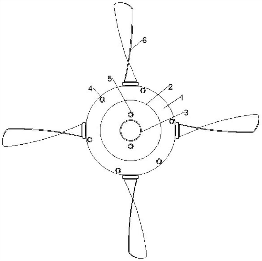
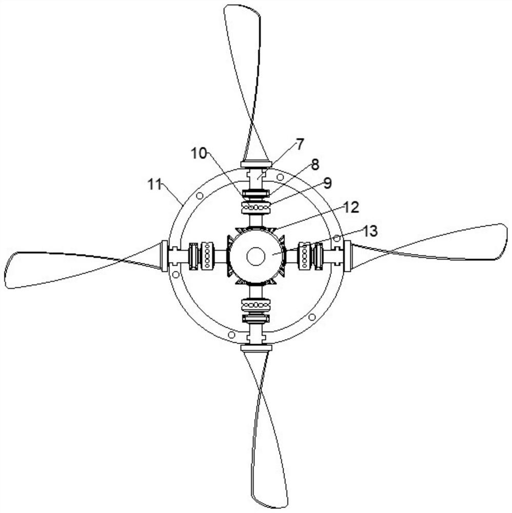
The invention discloses an adjustable impeller structure and hydroelectric equipment. The adjustable impeller structure comprises a shell and a rear cover detachably connected with the shell, and further comprises a plurality of blades, a rotating shaft penetrating through the side wall of the shell is fixed to the side, facing the shell, of each blade, a first bevel gear is fixed to the end, awayfrom the corresponding blade, of each rotating shaft, the first bevel gears are engaged with a second bevel gear rotationally mounted on the rear cover, and the second bevel gear is connected with anadjusting mechanism arranged on the outer side of the shell. A limiting disc is further installed on each rotating shaft, a plurality of limiting holes are formed in each limiting disc, and the limiting holes are matched with a clamping pin assembly arranged on the rear cover. The adjusting mechanism is separated from the rear cover, the clamping pin assembly is automatically separated from the limiting holes at the moment, the arranged adjusting mechanism drives the second bevel gear to rotate, and when the second bevel gear rotates, the rotating shafts and the blades connected with the rotating shafts are driven to rotate through rotation of the first bevel gears engaged with the second bevel gear, so that the placement angles of the blades are changed.

Description

Technical field[0001]The invention relates to the technical field related to hydropower generation, in particular to an adjustable impeller structure and hydropower generation equipment.Background technique[0002]Hydropower is the science and technology that studies technical and economic issues such as engineering construction and production operations that convert water energy into electrical energy. The water energy used by hydropower is mainly the potential energy stored in the water body. In order to convert water energy into electricity, different types of hydropower stations need to be built.[0003]Using rivers, lakes and other water with potential energy located at a high place to flow to a low place, the potential energy contained in it is converted into the kinetic energy of the water turbine, and then the water turbine is used as the driving force to drive the generator to produce electricity. Use hydraulic power (having a head) to push a hydraulic machine (water turbine) t...

Claims


Application Information

Patent Timeline
Patent Type & Authority Applications(China)
IPC IPC(8): F03B3/14
CPCF03B3/14F03B3/145Y02E10/20
Inventor 李冰李志龙
Owner 湖南新邵筱溪水电开发有限责任公司
Why Eureka
Try Eureka