
A sealing device for gas-liquid two-phase fluid medium under variable working conditions
A fluid medium and sealing device technology, which is applied in the direction of engine sealing, mechanical equipment, engine components, etc., can solve the problems of weak adaptability, poor sealing stability of gas-liquid two-phase fluid medium, etc., and achieve good throttling and pressure reduction, The effect of good sealing effect
- Summary
- Abstract
- Description
- Claims
- Application Information
AI Technical Summary
Problems solved by technology
Method used
Image

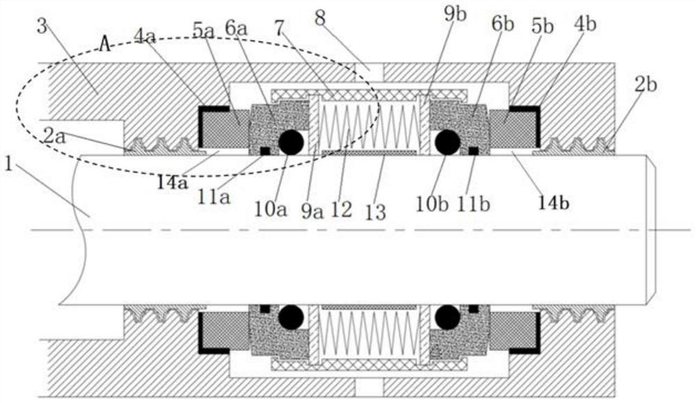
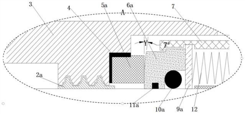
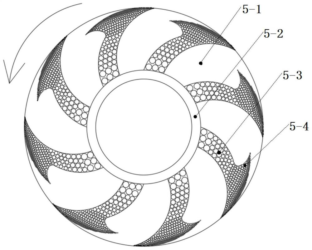
Examples
Embodiment Construction
[0028] Embodiments of the present invention are described in detail below, examples of which are shown in the drawings, wherein the same or similar reference numerals designate the same or similar elements or elements having the same or similar functions throughout. The embodiments described below by referring to the figures are exemplary only for explaining the present invention and should not be construed as limiting the present invention.
[0029] In describing the present invention, it should be understood that the terms "center", "longitudinal", "transverse", "length", "width", "thickness", "upper", "lower", "front", " Back", "Left", "Right", "Vertical", "Horizontal", "Top", "Bottom", "Inner", "Outer", "Axial", "Radial", "Circumferential", etc. The indicated orientation or positional relationship is based on the orientation or positional relationship shown in the drawings, and is only for the convenience of describing the present invention and simplifying the description,...
PUM
 Abstract
Description
Claims
Application Information