Supercharge Your Innovation With Domain-Expert AI Agents!

Vertical cold heading forming equipment for bolts

A molding equipment, vertical technology, applied in the direction of bolts, metal processing equipment, threaded fasteners, etc., can solve the problems of bolt extrusion damage, ejector rod damage of the ejector mechanism, inconvenient production and other problems, and achieve a simplified structure , The effect of simplifying the cold heading process steps and convenient operation

Inactive Publication Date: 2020-12-29
冯建娟
View PDF0 Cites 2 Cited by
  • Summary
  • Abstract
  • Description
  • Claims
  • Application Information

AI Technical Summary

Problems solved by technology

[0007] At present, this kind of bolt cold heading process steps is not only complicated, but also requires operators to follow the above steps. Once an error occurs in the cold heading process steps, the bolts will be squeezed and damaged, and even the ejection mechanism of the bolt cold heading equipment will be damaged. The problem of being damaged, for example, in the process of controlling the die to be close to the fixed die and performing cold heading, the operator makes an operation error to control the ejection of the cylinder of the ejector mechanism, or when the operator controls the ejection of the cylinder of the ejector mechanism, the operator If there is an operation error to control the die close to the fixed die and perform cold heading, the bolts will be squeezed and damaged, and even the ejector rod of the ejector mechanism will be damaged.
[0008] In order to solve the above problems, the inventor of this application submitted the application number 2020108222250 on August 16, 2020, and the name of the invention is a vertical bolt forming machine. During the process, it was found that the horizontal bolt forming equipment in this case had a complicated structure, which was not convenient for actual production.

Method used


Image

  • Vertical cold heading forming equipment for bolts
  • Vertical cold heading forming equipment for bolts
  • Vertical cold heading forming equipment for bolts

Examples


specific Embodiment 1

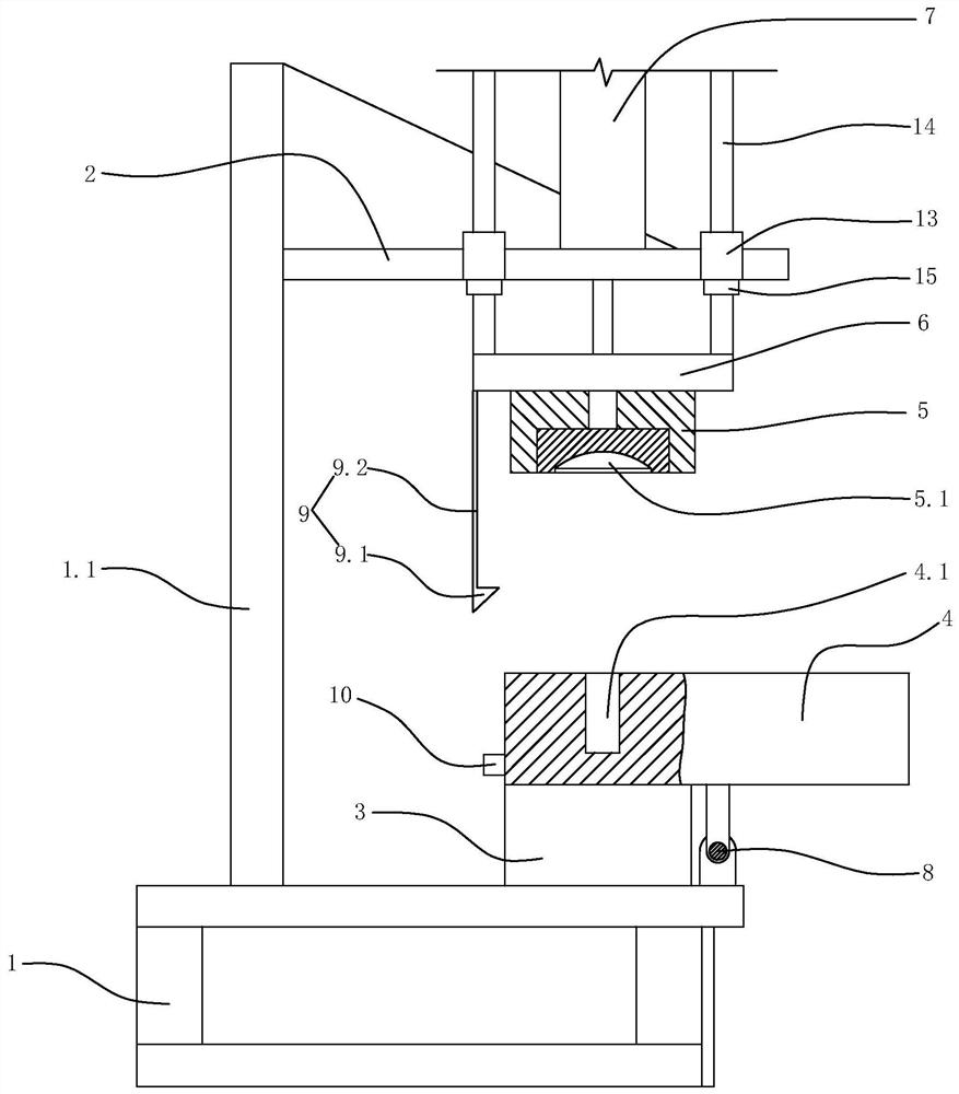
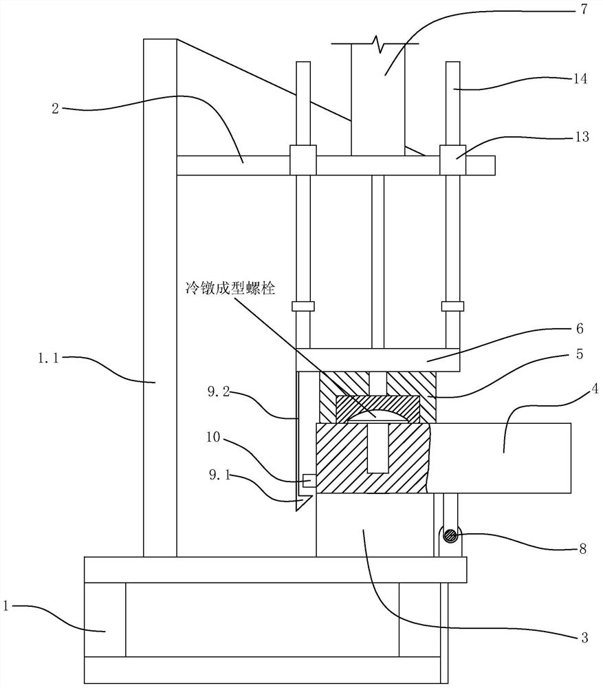
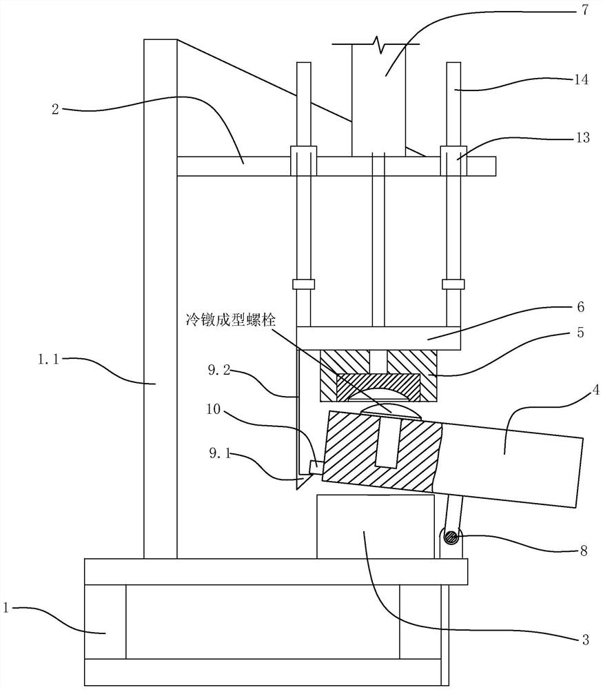
[0044] Specific embodiment 1: as figure 1 As shown, a bolt vertical cold heading forming equipment includes a base frame 1, a column 1.1 arranged on the base frame, an upper bracket 2 fixed on the upper part of the column, a lifting bracket 6 located below the upper bracket, and an upper bracket arranged on the upper bracket. The lifting actuator 7 for lifting the lifting bracket, the punching die 5 arranged on the lifting bracket, the bolt head forming hole 5.1 arranged on the lower surface of the punching die, and the rotating module arranged on the chassis through the rotation of the horizontal shaft 8 4. The stud limit hole set on the rotating module 4.1, the reference block 3 arranged on the bottom frame for positioning the rotating module, the clamping block 10 arranged on the outer surface of the rotating module and the lifting bracket arranged on it Elastic hook 9. The opening of the bolt head forming hole faces the datum block. The lower surface of the die where the...


PUM


Abstract

The invention discloses vertical cold heading forming equipment for bolts. According to the vertical cold heading forming equipment for the bolts, the structure as well as cold heading process steps of the bolts can be effectively simplified; and meanwhile, the problem that the bolts are extruded and damaged due to the fact that the cold heading process steps of the bolts get wrong can be effectively solved. The vertical cold heading forming equipment for bolts comprises a bottom frame, a stand column arranged on the bottom frame, an upper support fixedly arranged to the upper portion of the stand column, a lifting support located below the upper support, a lifting executing mechanism arranged on the upper support and used for lifting the lifting support, a stamping die arranged on the lifting support, a bolt head forming hole formed in the lower surface of the stamping die, a rotating module rotationally arranged on the bottom frame through a horizontal shaft rod, a stud limiting holeformed in the rotating module, a reference block arranged on the bottom frame and used for positioning the rotating module, a clamping block arranged on the outer side face of the rotating module aswell as an elastic clamping hook arranged on the lifting support.

Description

technical field [0001] The invention relates to bolt processing equipment, in particular to a vertical cold heading forming equipment for bolts. Background technique [0002] Cold heading is a forging method that uses a mold to upset (usually local upsetting) a metal bar at room temperature. It is usually used to manufacture the heads of screws, bolts, rivets, etc., which can reduce or replace cutting processing. The current bolt cold heading equipment generally needs to be equipped with an ejection mechanism, and its cold heading process generally includes the following four steps, [0003] First, put the rod on the fixed mold; [0004] Second, the cold heading equipment controls the die to be close to the fixed die, and performs cold heading to make the head of the bolt cold-headed in the forming hole, and then the die is separated from the fixed die; [0005] Third, through the cylinder of the ejector mechanism, the cold-headed bolts left on the fixed mold are ejected; ...

Claims


Application Information

Patent Timeline
Patent Type & Authority Applications(China)
IPC IPC(8): B21J9/06B21J13/08B21K1/46
CPCB21J9/06B21J13/085B21K1/46
Inventor 冯建娟
Owner 冯建娟
Features
  • R&D
  • Intellectual Property
  • Life Sciences
  • Materials
  • Tech Scout
  • Unparalleled Data Quality
  • Higher Quality Content
  • 60% Fewer Hallucinations
Learn More