Solid wood table board splicing device for furniture processing
A splicing device and wooden table technology, which is applied to the jointing of wooden veneers, adhesive application devices, wood processing appliances, etc., can solve the problems of low work efficiency and manpower consumption, so as to improve work efficiency, simple operation and save manpower Effect
- Summary
- Abstract
- Description
- Claims
- Application Information
AI Technical Summary
Problems solved by technology
Method used
Image
Examples
Embodiment 1
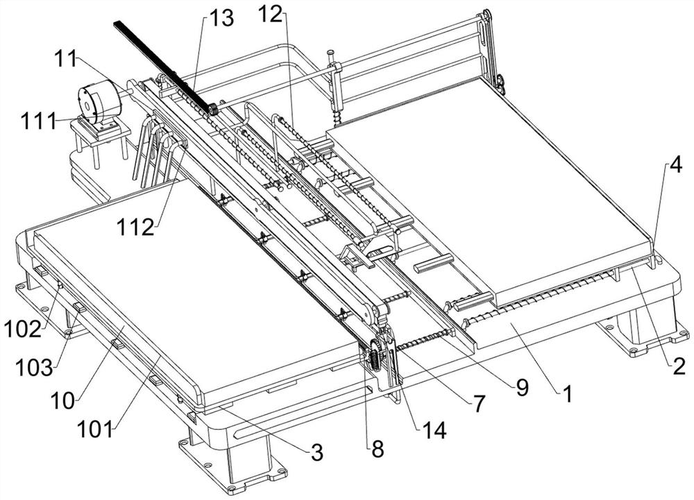
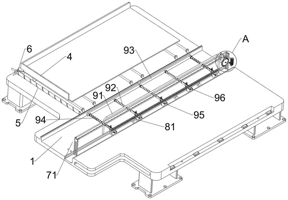
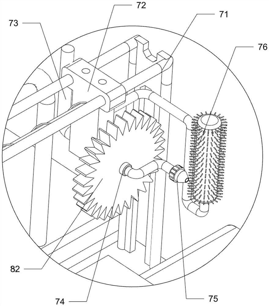
[0032] A solid wood table board splicing device for furniture processing, such as Figure 1-5 As shown, it includes a support 1, a first guide rail 2, a placement plate 3, a slide plate 4, a threaded rod 5 and a first fixing rod 6, and the right side of the top of the support 1 is connected with multiple sets of first guide rails 2 at even intervals. 1. A placement plate 3 is connected to the left side of the top, a slide plate 4 is slidably connected between multiple sets of first guide rails 2, a threaded rod 5 is rotatably connected to the rear side of the support 1, and a first fixed rod 6 is connected to the slide plate 4. A fixed rod 6 is threadedly matched with the threaded rod 5, and also includes a gluing assembly 7, a first rotating assembly 8, an insertion assembly 9 and a limit assembly 10, and the support 1 is provided with a gluing assembly 7 and an insertion assembly 9. A first rotating assembly 8 is provided between the glue assembly 7 and the support 1 , and a...
Embodiment 2
[0039] On the basis of Example 1, such as Figure 7 As shown, the clamping assembly 14 is also included, and the clamping assembly 14 includes a second sliding plate 141, a tension spring 142, a handle 143 and a third compression spring 144, and the top of the slider 72 is slidably connected to the second sliding plate 141 , a tension spring 142 is connected between the second sliding plate 141 and the slider 72, the second sliding plate 141 is in contact with the second guide rail 71, a handle 143 is connected to the rear side of the second sliding plate 141, the slider 72 is in contact with the second guide rail A third compression spring 144 is connected between 71 .
[0040] Initially, the extension spring 142 is in a stretched state, and when the slider 72 moves backward, it drives the second sliding plate 141 to move backward and makes the third compression spring 144 compressed. When the second sliding plate 141 moves backward to no When touching the second guide rail ...
Embodiment 3
[0042] On the basis of Example 2, such as Figure 6-7 As shown, a drive assembly 11 is also included, and the drive assembly 11 includes a servo motor 111, a mounting frame 112, a drive belt 113 and a connecting block 114. The servo motor 111 is installed on the left rear side of the top of the support 1, and the left side of the top of the support 1 Mounting frame 112 is connected, and on the mounting frame 112, the drive belt 113 is connected in rotation, the rear transmission shaft of driving belt 113 is connected with the output shaft of servo motor 111, and connecting block 114 is connected on the driving belt 113, and connecting block 114 is connected with the first The two sliding plates 141 cooperate.
[0043] When it is necessary to pull the slider 72 to move, the servo motor 111 can be started to drive the driving belt 113 to rotate, and the driving belt 113 rotates to drive the connecting block 114 to rotate, and the connecting block 114 pushes the second sliding pl...
PUM
 Abstract
Description
Claims
Application Information
 - R&D
- Intellectual Property
- Life Sciences
- Materials
- Tech Scout
- Unparalleled Data Quality
- Higher Quality Content
- 60% Fewer Hallucinations
Browse by: Latest US Patents, China's latest patents, Technical Efficacy Thesaurus, Application Domain, Technology Topic, Popular Technical Reports.
© 2025 PatSnap. All rights reserved.Legal|Privacy policy|Modern Slavery Act Transparency Statement|Sitemap|About US| Contact US: help@patsnap.com


