Shock absorber signal disc structure

A shock absorber and signal plate technology, applied in the design characteristics of spring/shock absorber, spring/shock absorber, machine/engine, etc., can solve the problems of insufficient connection and troublesome installation, and achieve convenient installation and weight reduction. Cost, effect of reducing angle deviation

Pending Publication Date: 2020-12-29
GUANGXI YUCHAI MASCH CO LTD
View PDF0 Cites 0 Cited by
  • Summary
  • Abstract
  • Description
  • Claims
  • Application Information

AI Technical Summary

Problems solved by technology

[0002] Due to structural layout problems, the existing range-extended engines usually arrange the crankshaft speed sensor and the signal plate at the front end of the engine, and the shock absorber and the signal plate are mostly in a separate structure, and the signal plate needs to be installed on the shock absorber with bolts to provide ECU control signal parameters such as crankshaft speed and phase; in the existing structure, the installation is troublesome and the connection is not firm enough

Method used


Image

  • Shock absorber signal disc structure
  • Shock absorber signal disc structure
  • Shock absorber signal disc structure

Examples


Embodiment Construction

[0019] Below in conjunction with embodiment, the present invention is further described, but does not constitute any restriction to the present invention, anyone makes the limited number of amendments in the scope of claims of the present invention, still within the scope of claims of the present invention.

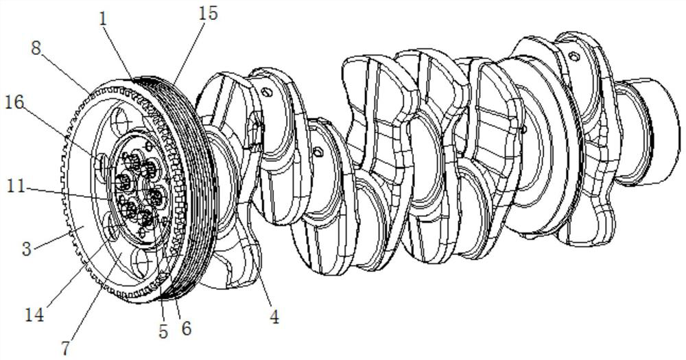
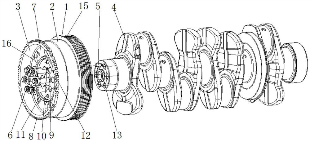
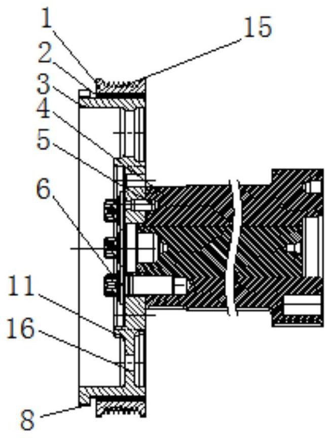
[0020] The specific embodiment of the present invention is like this: with reference to Figure 1-3 As shown, a signal plate structure of a shock absorber includes a shock absorber outer ring 1, a wheel groove 15, a rubber part 2, a shock absorber inner ring 3, a crankshaft 4, a positioning pin 5 and a connecting bolt 6, and the wheel groove 15 is set On the outer ring 1 of the shock absorber, the outer ring 1 of the shock absorber is sleeved on the rear end of the inner ring 3 of the shock absorber, and the rubber part 2 is arranged between the inner wall of the outer ring 1 of the shock absorber and the outer wall of the inner ring 3 of the shock absorber The inner ring...


PUM


Abstract

The invention discloses a shock absorber signal disc structure which comprises a shock absorber outer ring, a rubber part, a shock absorber inner ring, a crankshaft, a positioning pin and a connectingbolt. The shock absorber inner ring is provided with a connecting disc connected with the end face of the crankshaft. The positioning pin and the connecting bolt are arranged on the connecting disc.The outer wall of the front end of the shock absorber inner ring is provided with a circle of signal teeth in a protruding manner. The shock absorber signal disc structure belongs to the technical field of engines. The structure is convenient to install. The signal teeth are integrated on the shock absorber inner ring. A shock absorber and a signal disc are integrated. The number of parts is reduced. The weight and cost are reduced. The assembling difficulty is reduced. The signal teeth are integrated on the shock absorber inner ring, namely, the signal teeth are integrated on a shock absorberinner wheel, angle machining is ensured, the angle deviation can be further reduced, and signal obtaining reliability is improved. The problem that due to overlapping of a positioning hole, a bolt hole and the like, the angle of the signal disc deviates to a certain degree is reduced.

Description

technical field [0001] The present invention relates to engine technology, and more particularly, it relates to a shock absorber signal disc structure. Background technique [0002] Due to structural layout problems, the existing range-extended engines usually arrange the crankshaft speed sensor and the signal plate at the front end of the engine, and the shock absorber and the signal plate are mostly in a separate structure, and the signal plate needs to be installed on the shock absorber with bolts to provide ECU control signal parameters such as crankshaft speed and phase; in the existing structure, the installation is troublesome and the connection is not firm enough. Contents of the invention [0003] The technical problem to be solved by the present invention is to solve some of the above-mentioned deficiencies in the prior art. The purpose of the present invention is to provide a shock absorber signal plate structure that is easy to install. [0004] In order to ac...

Claims


Application Information

Patent Timeline
Patent Type & Authority Applications(China)
IPC IPC(8): F16F15/12F16F15/26G01P3/44F02B77/08
CPCF02B77/08F16F15/1207F16F15/26F16F2230/0005F16F2230/0029F16F2230/08G01P3/44
Inventor 韦莹梁德浦张锦苏怀林何化
Owner GUANGXI YUCHAI MASCH CO LTD
Why Eureka
Try Eureka