
Riverway flow velocity video monitoring device and method based on deep learning
A technology of video monitoring and deep learning, applied in measuring devices, velocity/acceleration/impact measurement, fluid velocity measurement, etc., can solve the problems of obtaining flood data in previous years, slow calculation speed, difficulty in measuring river flow, etc., and achieve anti-accident risk powerful effect
- Summary
- Abstract
- Description
- Claims
- Application Information
AI Technical Summary
Problems solved by technology
Method used
Image

Examples
Embodiment
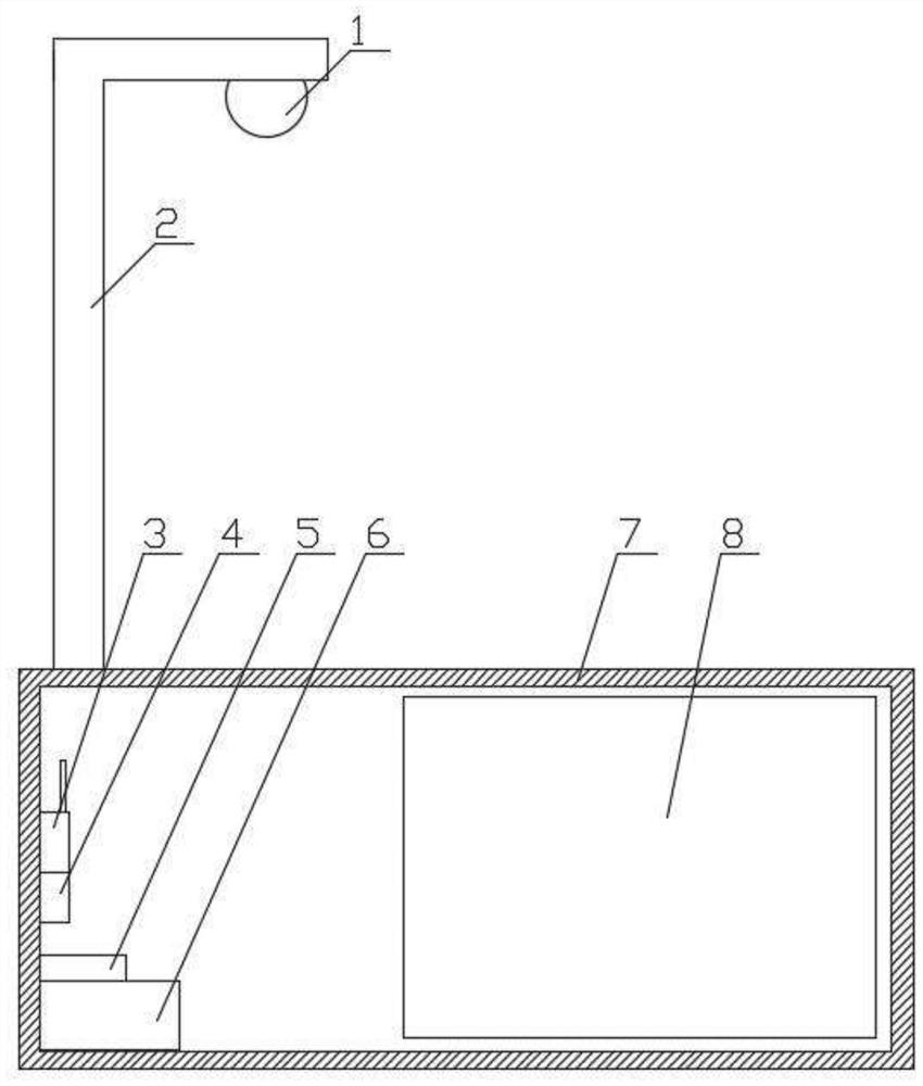
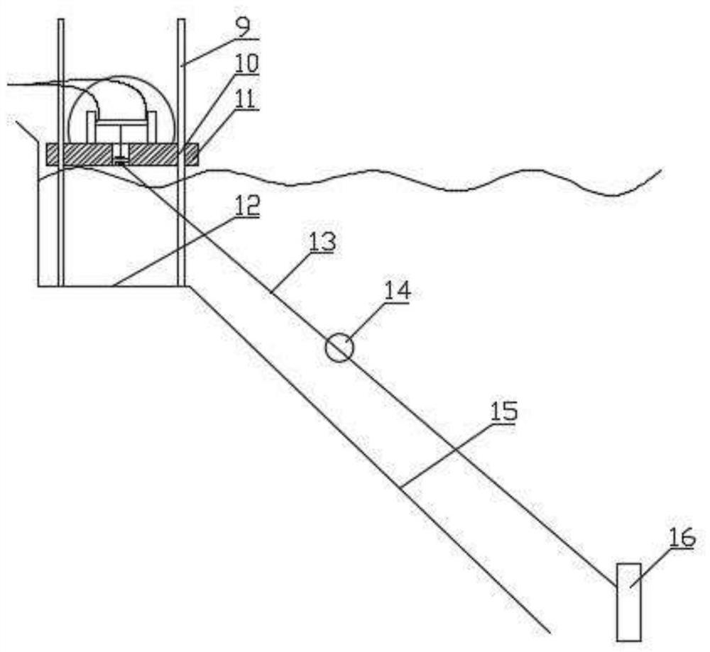
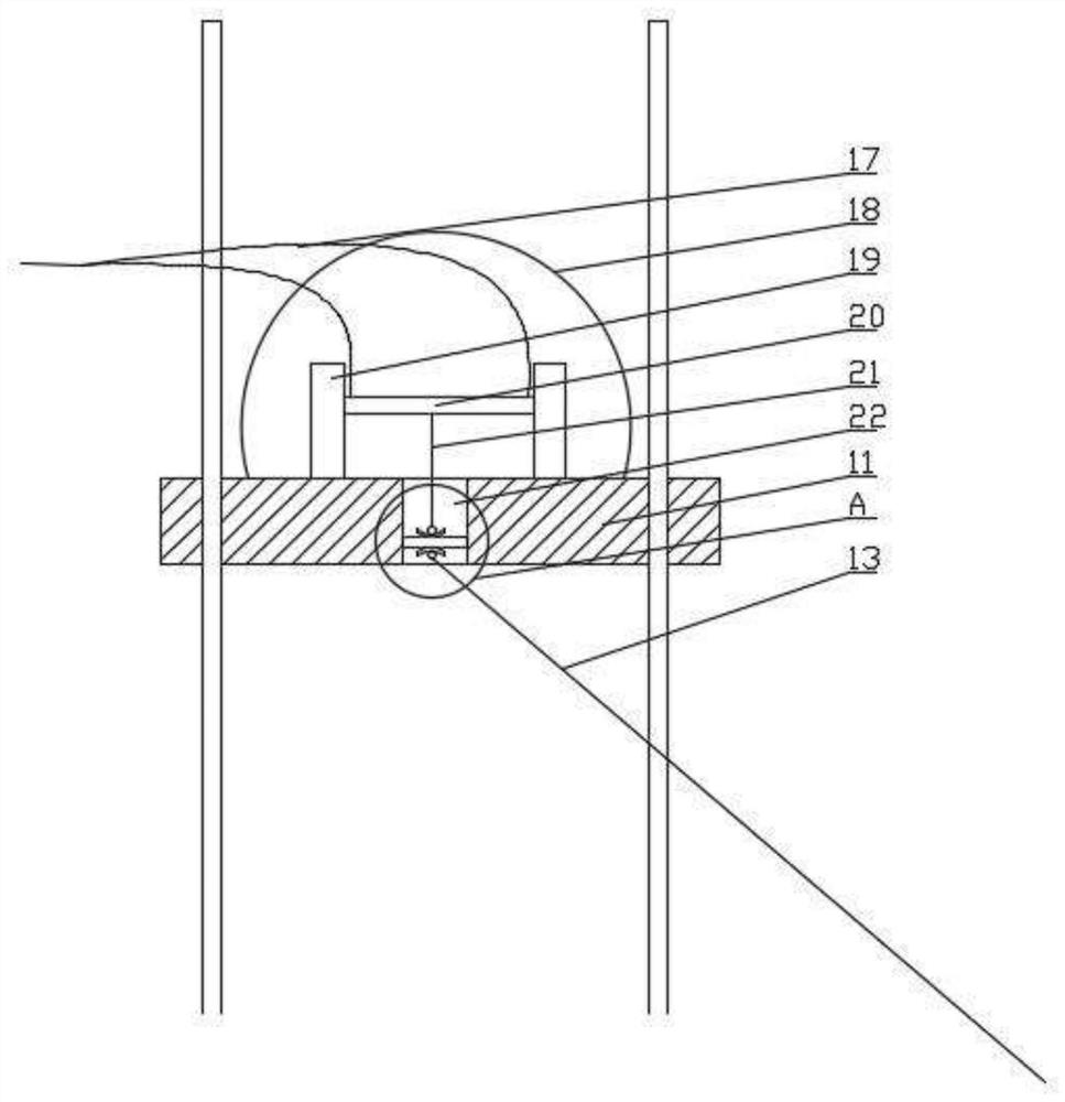
[0051] Such as Figure 1-12 Shown: a video monitoring device for river flow velocity based on deep learning, including a monitoring terminal and a monitoring center. The monitoring terminal includes an equipment box 7, and a pole 2 is arranged above the equipment box 7. A monitoring unit 1 is set at the upper end, a control unit 4, a power supply unit and a communication unit 3 are set in the equipment box 7, and a beacon supplementary unit 8 is also set in the equipment box 7;
[0052] The control unit 4 is connected with the monitoring unit 1 , the communication unit 3 , and the beacon supplementary unit 8 , and the control unit 4 is connected with the monitoring center through the communication unit 3 .
[0053] The monitoring unit 1 includes a monitoring camera installed on the upper end of the pole 2 .
[0054] The control unit 4 includes a microcontroller, and the communication unit 3 adopts wired or wireless transmission methods.
[0055] The power supply unit include...
PUM
 Abstract
Description
Claims
Application Information