
A fiber scanner

A technology of optical fiber scanning and optical fiber, which is applied in the field of optical fiber scanning, can solve the problems of easy fatigue, looseness of the connection part, use stability and service life difficult to meet the use requirements, etc., and achieve the effect of enhancing independence, reducing deformation, and increasing rigidity

Active Publication Date: 2022-08-09
CHENGDU IDEALSEE TECH
View PDF0 Cites 0 Cited by
  • Summary
  • Abstract
  • Description
  • Claims
  • Application Information

AI Technical Summary

Problems solved by technology

At present, the fixing methods of optical fibers are mostly glued or welded, that is, the optical fiber is glued or welded to the outer surface or inner hole of the piezoelectric material tube, but because the piezoelectric material tube itself vibrates through stretching and deformation, this makes the optical fiber and The connection between piezoelectric material tubes is prone to fatigue and looseness, and the stability and service life are difficult to meet the requirements of use

Method used


Image

  • A fiber scanner
  • A fiber scanner
  • A fiber scanner

Examples


Embodiment Construction

[0031]The technical solutions in the embodiments of the present invention will be clearly and completely described below with reference to the accompanying drawings in the embodiments of the present invention. Obviously, the described embodiments are only a part of the embodiments of the present invention, but not all of the embodiments. Based on the embodiments of the present invention, all other embodiments obtained by those of ordinary skill in the art without creative efforts shall fall within the protection scope of the present invention.

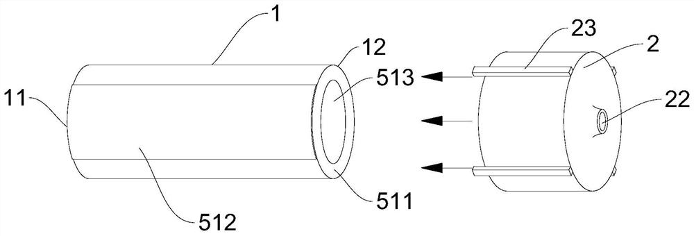
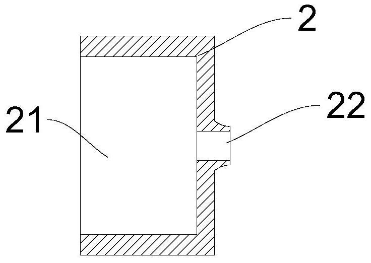
[0032] like Figure 1-3 As shown, an embodiment of the present invention provides an optical fiber scanner, which includes a first piezoelectric material tube actuator 1, a tip kit 2 and an optical fiber. The axial ends of the first piezoelectric material tube actuator 1 are respectively The fixed end 11 and the free end 12, the free end 12 of the first piezoelectric material tube actuator 1 vibrates in at least one direction perpendic...


PUM


Abstract

The invention discloses an optical fiber scanner, which comprises a first piezoelectric material tube actuator, an end sleeve and an optical fiber. The axial ends of the first piezoelectric material tube actuator are a fixed end and a free end respectively. The head kit is fixedly arranged on the free end of the first piezoelectric material tube actuator, the end head kit is provided with an optical fiber installation hole penetrating itself, the optical fiber is penetrated in the first piezoelectric material tube actuator, and the end of the optical fiber is The part of the optical fiber passing through the optical fiber installation hole forms the optical fiber cantilever, and the part of the optical fiber close to the optical fiber cantilever is fixedly connected with the optical fiber installation hole. The structure of the fixed connection between the end kit and the piezoelectric material tube actuator, and the connection between the optical fiber and the end kit ensures that the optical fiber connection structure is not affected by the deformation of the piezoelectric material tube actuator, and the stability of the connection part is guaranteed. Long life and reliable fixation.

Description

technical field [0001] The invention relates to the technical field of optical fiber scanning, in particular to an optical fiber scanner. Background technique [0002] The piezoelectric material tube actuator is generally a two-way electrode actuator or a four-way electrode actuator. The piezoelectric material tube actuator includes a piezoelectric material tube, and the outer surface of the piezoelectric material tube is provided with one or two pairs of The piezoelectric material tube has an axis-symmetrical outer electrode, and the inner surface of the piezoelectric material tube is provided with an inner electrode matched with the outer electrode. The part of the piezoelectric material tube located between the outer electrode and the corresponding inner electrode is polarized in the radial direction, so that when the inner electrode and the outer electrode are connected to the external driving device, the free end of the piezoelectric actuator is aligned along its corres...

Claims


Application Information

Patent Timeline
Patent Type & Authority Patents(China)
IPC IPC(8): G02B26/10H02N2/04
CPCG02B26/103H02N2/04
Inventor 不公告发明人
Owner CHENGDU IDEALSEE TECH
Learn More