Small motor machining system and method
A technology for processing systems and small motors, which is applied in the manufacture of motor generators, electrical components, electromechanical devices, etc., and can solve problems such as cumbersome operation and inability to stabilize motor locking and assembly
- Summary
- Abstract
- Description
- Claims
- Application Information
AI Technical Summary
Problems solved by technology
Method used
Image
Examples
specific Embodiment approach 1
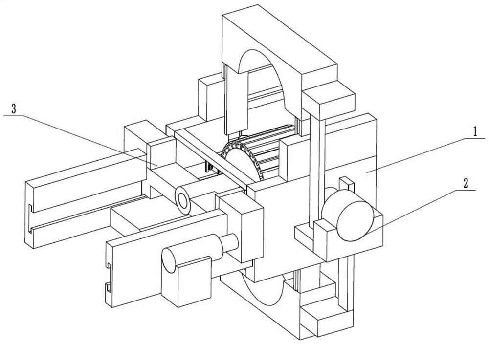
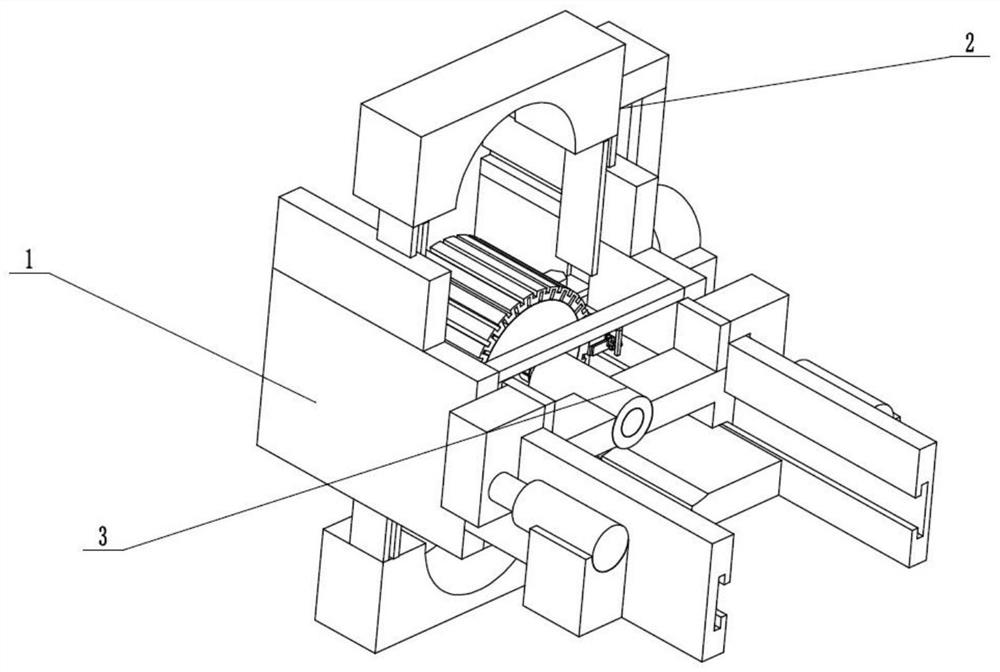
[0034] Such as Figure 1 to Figure 11 As shown, a small motor processing system includes a motor adding frame 1, a stable combination adder 2, a rotor adder 3, an added motor rotor 4, an added motor combination upper casing 5 and an added motor combination lower casing 6. The above-mentioned stable combination adder 2 is longitudinally slidably connected in the motor adder frame 1, the rotor adder 3 is horizontally slidably connected in the motor adder frame 1, the stable combination adder 2 is socketed on the adder motor rotor 4, and the adder motor rotor 4 Clearance fit Between the upper housing 5 of the added motor combination and the lower housing 6 of the added motor combination, the upper housing 5 of the added motor combination and the lower housing 6 of the added motor combination are mutually clearance fit, and the stable combined adder 2 passes through the magnet Adsorption adds motor combination upper casing 5 and adds motor combination lower casing 6. The added mo...
specific Embodiment approach 2
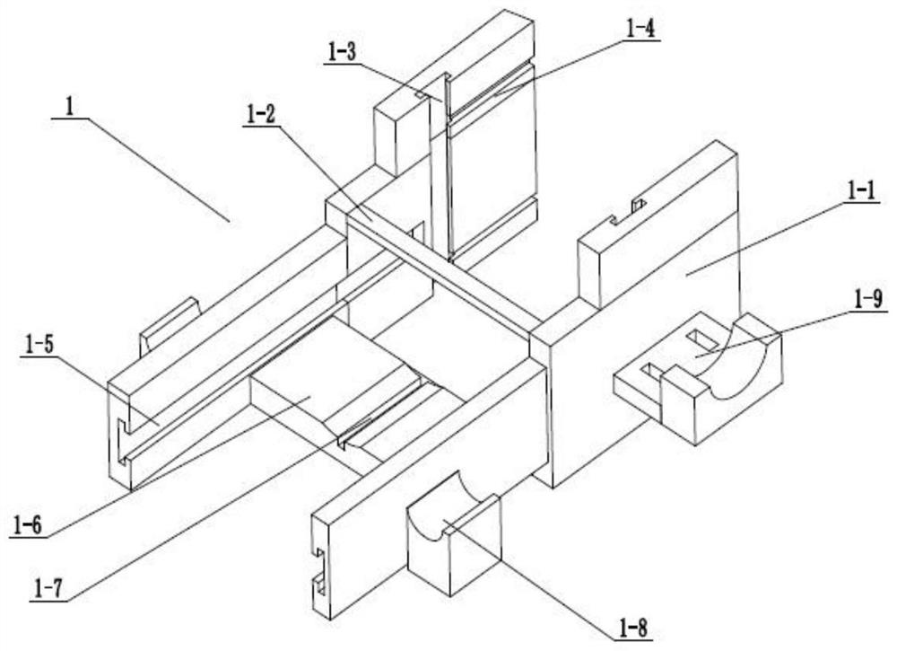
[0036] Such as Figure 1 to Figure 11 As shown, this embodiment further explains Embodiment 1. The motor add-on frame 1 includes two assembly processing frame plates 1-1, two connecting plates 1-2, longitudinally adding chute 1-3, and a housing Add inner chute 1-4 horizontally, add inner chute 1-5 horizontally for rotor, rotor loading platform 1-6, rotor loading slot 1-7, two electric telescopic rod fixing seats 1-8 and motor fixing platform 1-9, the two assembly processing frame plates 1-1 are connected by two connecting plates 1-2, the inner walls of the two assembly processing frame plates 1-1 are provided with longitudinal adding chute 1-3, the assembly processing frame The upper and lower sides of the inner wall of the plate 1-1 are provided with a horizontally added inner chute 1-4 of the shell, and the left end of the inner wall of the assembly processing frame plate 1-1 is provided with a rotor transversely added inner chute 1-5, and the rotor is in the form of a carri...
specific Embodiment approach 3
[0038] Such as Figure 1 to Figure 11 As shown, this embodiment will further illustrate Embodiment 2. The stable combination adder 2 includes an adding drive motor 2-1, an adding drive gear 2-2, two driving racks 2-3, and two connecting platforms 2-4. Two additional extrusion frames 2-5 and adsorption sliding seat 2-6, the additional drive motor 2-1 is fixedly connected to the motor fixing table 1-9, and the additional drive gear 2-2 is fixedly connected to the additional drive motor On the transmission shaft of 2-1, the two ends of the driving gear 2-2 are respectively meshed with the two driving racks 2-3 for transmission, and the two driving racks 2-3 are longitudinally slidably connected to the motor fixing table 1-9 Inside, the two connecting platforms 2-4 are respectively fixedly connected to the two driving racks 2-3, and the two connecting platforms 2-4 are respectively fixedly connected to the two additional extrusion frames 2-5, and the additional extrusion frame 2 ...
PUM
 Abstract
Description
Claims
Application Information
 - R&D
- Intellectual Property
- Life Sciences
- Materials
- Tech Scout
- Unparalleled Data Quality
- Higher Quality Content
- 60% Fewer Hallucinations
Browse by: Latest US Patents, China's latest patents, Technical Efficacy Thesaurus, Application Domain, Technology Topic, Popular Technical Reports.
© 2025 PatSnap. All rights reserved.Legal|Privacy policy|Modern Slavery Act Transparency Statement|Sitemap|About US| Contact US: help@patsnap.com


