Rapid forming die for capacitor cover plate machining

A capacitor cap and forming mold technology, which is applied in capacitors, capacitor manufacturing, circuits, etc., can solve the problems of manpower consumption and low efficiency, and achieve the effects of improving work efficiency, avoiding damage, and stabilizing device operation

Active Publication Date: 2021-01-01
宁国市红宁橡塑制品有限公司
View PDF7 Cites 0 Cited by
  • Summary
  • Abstract
  • Description
  • Claims
  • Application Information

AI Technical Summary

Problems solved by technology

[0004] The purpose of the present invention is to solve the problems of labor-intensive and low efficiency in the prior art, and propose a rapid prototyping mold for capacitor cover plate processing

Method used


Image

  • Rapid forming die for capacitor cover plate machining
  • Rapid forming die for capacitor cover plate machining
  • Rapid forming die for capacitor cover plate machining

Examples


Embodiment 1

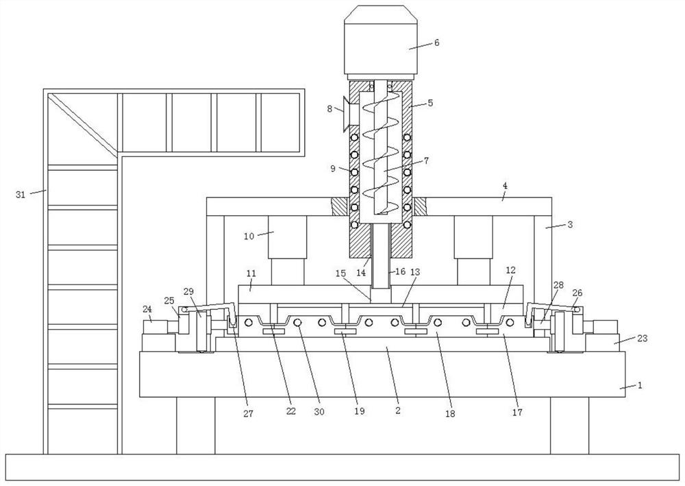
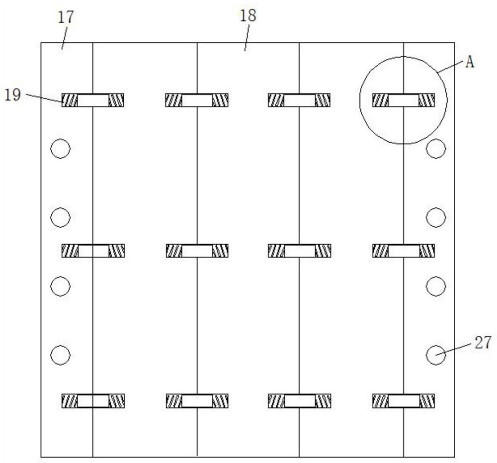
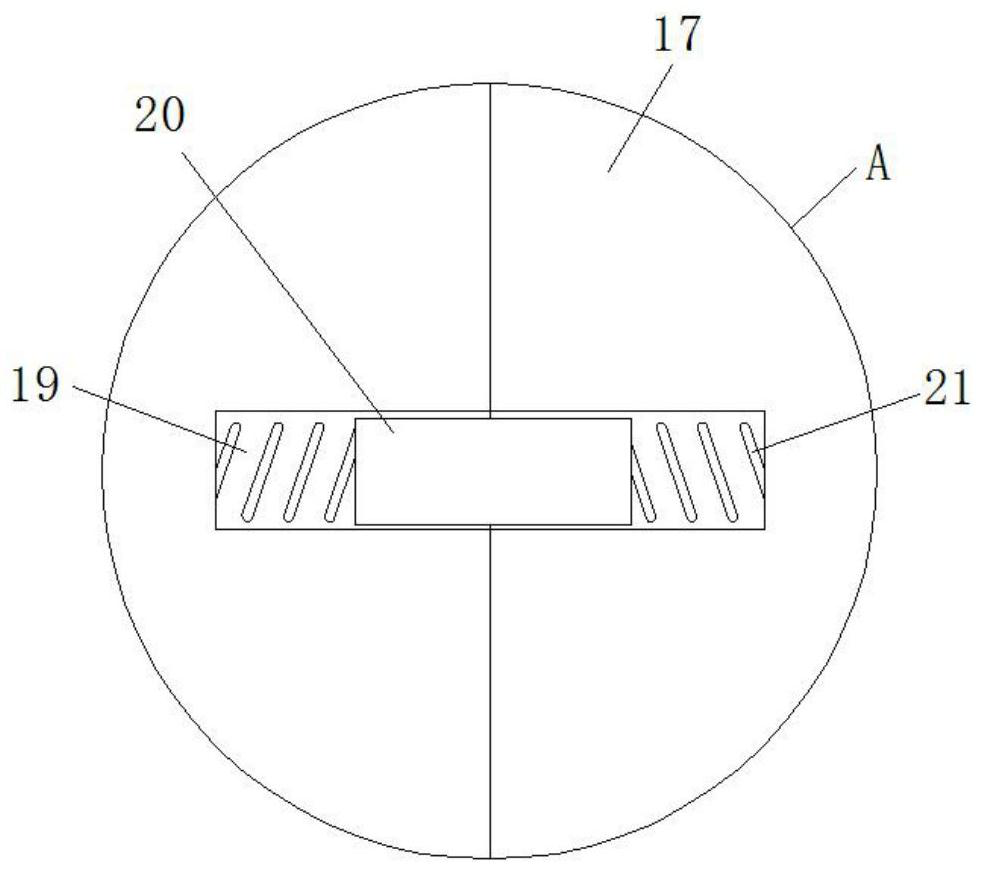
[0027] refer to Figure 1-4 , a rapid prototyping mold for capacitor cover plate processing, comprising a forming table 1, a support plate 2 is fixed in the middle of the top surface of the forming table 1, a support column 3 is fixed on the top surface of the forming table 1, and the top of the support column 3 is fixed with a mounting plate by screws. Plate 4, a through hole is opened in the middle of the mounting plate 4, the inner wall of the through hole is fixed with the injection barrel 5 by screws, the top surface of the injection barrel 5 is fixed with a servo motor 6 by screws, and the output end of the servo motor 6 passes through the injection The top surface of the barrel 5 is fixedly connected with a filling auger 7, and a filling hole is provided on one side of the upper end of the filling barrel 5, and the inner wall of the filling hole is fixed with a filling funnel 8 by screws, and a heating tube 8 is also provided inside the filling barrel 5. Pipe one 9, bot...

Embodiment 2

[0030] Such as figure 1 As shown, this embodiment is basically the same as Embodiment 1. Preferably, a feeding rack 31 is provided on one side of the molding table 1, and the feeding rack 31 is fixedly connected to the working surface, and the upper end of the feeding rack 31 is located at the feeding funnel. 8 sides.

[0031] In this embodiment, a loading frame 31 is provided on one side of the molding table 1, so as to facilitate the loading operation of the injection molding material, and greatly improve the working efficiency of the production of the capacitor cover plate.

Embodiment 3

[0033] Such as figure 1 As shown, this embodiment is basically the same as Embodiment 1. Preferably, there are four support columns 3 distributed on the top surface of the forming table 1 in a rectangular shape.

[0034] In this embodiment, by providing four supporting columns 3, the fixing of the mounting plate 4 is more stable, thereby ensuring a more stable operation of the device.


PUM


Abstract

The invention discloses a rapid forming die for capacitor cover plate processing. The rapid forming die comprises a forming table. An abutting plate is fixed in the middle of the top surface of the forming table. Support columns are fixed on the top surface of the forming table. A mounting plate is fixed at the top ends of the support columns through screws. A through hole is formed in the middleof the mounting plate, and a material injection barrel barrel is fixedly connected to the inner wall of the through hole through screws. A servo motor is fixedly connected to the top face of the material injection barrel through screws. An output end of the servo motor penetrates through the top face of the material injection barrel and is fixedly connected with a material injection packing auger.A material adding hole is further formed in one side of the upper end of the material injection barrel, a material adding funnel is fixed to the inner wall of the material adding hole through screws,and first heating pipes are further arranged on the inner side of the material injection barrel. The rapid forming die for capacitor cover plate processing is reasonable in design and stable in operation, stress borne by a capacitor cover plate during chamfering die opening is reduced in a two-side die opening mode, therefore the capacitor cover plate die-casting quality is guaranteed, and the percent of pass of capacitor cover plate production is greatly improved.

Description

technical field [0001] The invention relates to the technical field of capacitor cover plate production equipment, in particular to a rapid prototyping mold for capacitor cover plate processing. Background technique [0002] Capacitors are two conductors that are close to each other, and a layer of non-conductive insulating medium is sandwiched between them. During the production of capacitors, the capacitor cover plate needs to be processed, which requires the use of forming molds. [0003] Existing capacitor cover molds usually use bottom ejection after processing. Since the capacitor cover is surrounded by chamfers, the chamfer is easy to be damaged by direct ejection, and the qualified rate of capacitor cover production is low, which greatly results in resources. waste, so it is necessary to study a rapid prototyping mold for capacitor cover plate processing. Contents of the invention [0004] The object of the present invention is to solve the problems of labor-inten...

Claims


Application Information

Patent Timeline
Patent Type & Authority Applications(China)
IPC IPC(8): B22D17/22B22D17/20H01G13/00
CPCB22D17/22B22D17/2007H01G13/00
Inventor 陈树林黄勇尹三同耿翠红陈天阳
Owner 宁国市红宁橡塑制品有限公司
Why Eureka
Try Eureka