Spring hanger capable of improving output rigidity and design method thereof

A spring hanger and stiffness technology, applied in the direction of springs/shock absorbers, coil springs, mechanical equipment, etc., can solve the problems of manufacturing difficulties, installation and production troubles, increase manufacturing costs and time, and achieve the effect of improving output stiffness.

Pending Publication Date: 2021-01-01
XIAN THERMAL POWER RES INST CO LTD
View PDF0 Cites 2 Cited by
  • Summary
  • Abstract
  • Description
  • Claims
  • Application Information

AI Technical Summary

Problems solved by technology

[0002] At present, some equipment or pipelines in the energy industries such as electric power and petrochemical industry need high-rigidity spring hangers to hang, and the outer diameter and diameter of the built-in springs are generally large, so it is difficult to manufacture; spring hangers with built-in high-rigidity springs still exist Unable to install in a narrow space and other problems, causing greater installation and production troubles
In addition, in industrial production, the inner spring is generally a standard part produced according to the corresponding sequence. If the stiffness of the required inner spring is not in the standard sequence under special circumstances, non-standard design and manufacture must be carried out, which greatly increases the manufacturing cost and time.

Method used


Image

  • Spring hanger capable of improving output rigidity and design method thereof

Examples


Embodiment Construction

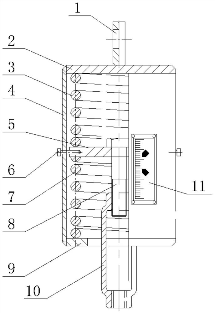
[0018] The present invention is described in further detail below in conjunction with accompanying drawing:

[0019] refer to figure 1 , the spring hanger that can improve the output stiffness of the present invention includes an upper end plate 2, a cylinder body 4, a lower end plate 9, a spring pressure plate 5, an upper spring 3, a lower spring 7, a hex head bolt 8, a turnbuckle screw 10 and a positioning Pin 6; the upper end plate 2 is fixed at the top opening of the cylinder 4, the lower end plate 9 is fixed at the bottom opening of the cylinder 4, the spring pressure plate 5 is located in the cylinder 4, and the upper spring 3 is located between the upper end plate 2 and the spring pressure plate 5 The lower spring 7 is located between the lower end plate 9 and the spring pressure plate 5; the lower end of the hex head bolt 8 passes through the middle of the spring pressure plate 5 and connects with the upper end of the turnbuckle screw 10, and the lower end of the turnb...


PUM


Abstract

The invention discloses a spring hanger capable of improving output rigidity and a design method thereof. The spring hanger comprises an upper end plate, a cylinder, a lower end plate, a spring pressing plate, an upper spring, a lower spring, a hexagonal head bolt, a turnbuckle and a positioning pin, wherein the upper end plate is fixed at a top opening of the cylinder; the lower end plate is fixed at a bottom opening of the cylinder; the spring pressing plate is positioned in the cylinder; the upper spring is positioned between the upper end plate and the spring pressing plate; the lower spring is positioned between the lower end plate and the spring pressing plate; the lower end of the hexagonal head bolt penetrates through the middle part of the spring pressing plate to connect with theupper end of the turnbuckle; the lower end of the turnbuckle penetrates through the lower end plate to extend out of the cylinder; a lug plate is arranged at the top of the upper end plate; multipleholes are formed in the side wall of the cylinder; and the positioning pin penetrates through the holes to insert in a groove hole in the outer peripheral surface of the spring pressing plate. The spring hanger and the design method thereof can improve the output rigidity of the spring hanger under the preconditions of not changing spring materials and not increasing the spring diameter and the outer diameter, and can satisfy the mounting demands in narrow space. In addition, the spring hanger with nonstandard output rigidity can be designed through a method of combining the upper spring withthe lower spring, so that the design and manufacturing costs and time of the spring hanger with nonstandard rigidity are greatly saved.

Description

technical field [0001] The invention belongs to the field of mechanical equipment manufacturing, and relates to a spring hanger capable of improving output stiffness and a design method thereof. Background technique [0002] At present, some equipment or pipelines in the energy industries such as electric power and petrochemical industry need high-rigidity spring hangers to hang, and the outer diameter and diameter of the built-in springs are generally large, so it is difficult to manufacture; spring hangers with built-in high-rigidity springs still exist It cannot be installed in a small space and other problems, causing greater installation and production troubles. In addition, in industrial production, the inner spring is generally a standard part produced according to the corresponding sequence. If the stiffness of the required inner spring is not in the standard sequence under special circumstances, non-standard design and manufacture must be carried out, which greatly ...

Claims


Application Information

Patent Timeline
Patent Type & Authority Applications(China)
IPC IPC(8): F16F1/13F16F1/06
CPCF16F1/06F16F1/13
Inventor 王军民陈盛广陈尚军程勇明王必宁安付立邓玲惠秦沫黄钟声
Owner XIAN THERMAL POWER RES INST CO LTD
Why Eureka
Try Eureka