Eureka AIR delivers breakthrough ideas for toughest innovation challenges, trusted by R&D personnel around the world.

Two-dimensional piezoelectric driving platform for suppressing orthogonal disturbance

A piezoelectric drive and electric drive technology, applied in the direction of piezoelectric effect/electrostrictive or magnetostrictive motors, electrical components, generators/motors, etc., can solve the problem that the stroke is easily affected by load changes, the output stiffness is small, Problems such as the orthogonal disturbance of the piezoelectric drive unit achieve the effect of enhancing the anti-disturbance ability, increasing the output stiffness, and enhancing the output stability

Pending Publication Date: 2022-07-12
GUANGZHOU UNIVERSITY
View PDF0 Cites 1 Cited by
  • Summary
  • Abstract
  • Description
  • Claims
  • Application Information

AI Technical Summary

Problems solved by technology

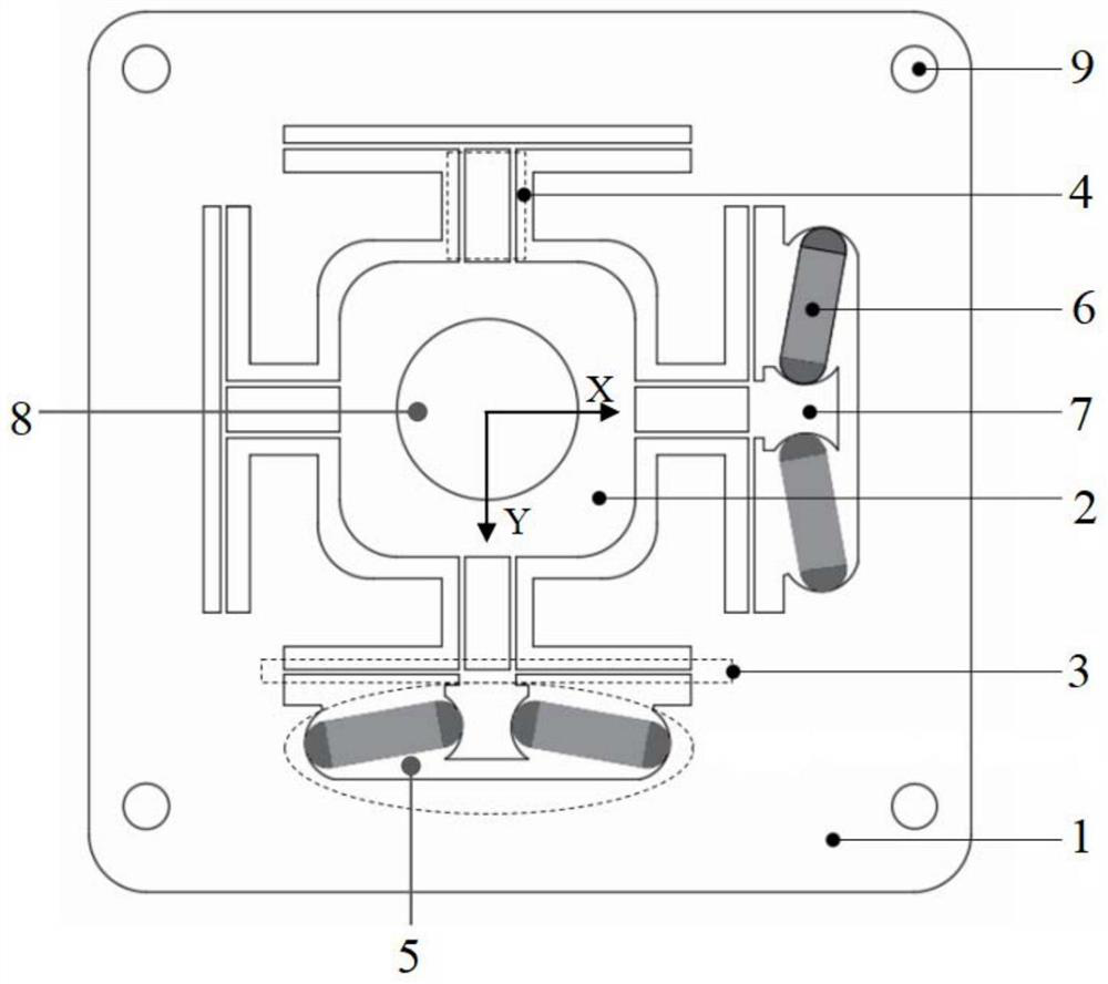
[0008] The purpose of the present invention is to provide a two-dimensional piezoelectric drive platform that suppresses orthogonal disturbances. The piezoelectric drive platform can achieve anti-orthogonal disturbances, stabilize output displacement as the goal, and solve the problem of the small output stiffness of traditional parallel piezoelectric actuators. , the stroke is easily affected by load changes, and there is a problem of orthogonal disturbance between piezoelectric drive units

Method used


Image

  • Two-dimensional piezoelectric driving platform for suppressing orthogonal disturbance
  • Two-dimensional piezoelectric driving platform for suppressing orthogonal disturbance
  • Two-dimensional piezoelectric driving platform for suppressing orthogonal disturbance

Examples


Embodiment Construction

[0027] The technical solutions of the present invention will be clearly and completely described below with reference to the embodiments. Obviously, the described embodiments are part of the embodiments of the present invention, but not all of the embodiments. Based on the embodiments of the present invention, all other embodiments obtained by those of ordinary skill in the art without creative efforts shall fall within the protection scope of the present invention.

[0028] In the description of the present invention, it should be understood that the terms "center", "longitudinal", "lateral", "length", "width", "thickness", "top", "bottom", "front", " Or The positional relationship is based on the orientation or positional relationship shown in the accompanying drawings, which is only for the convenience of describing the present invention and simplifying the description, rather than indicating or implying that the referred device or element must have a specific orientation, ...


PUM


Abstract

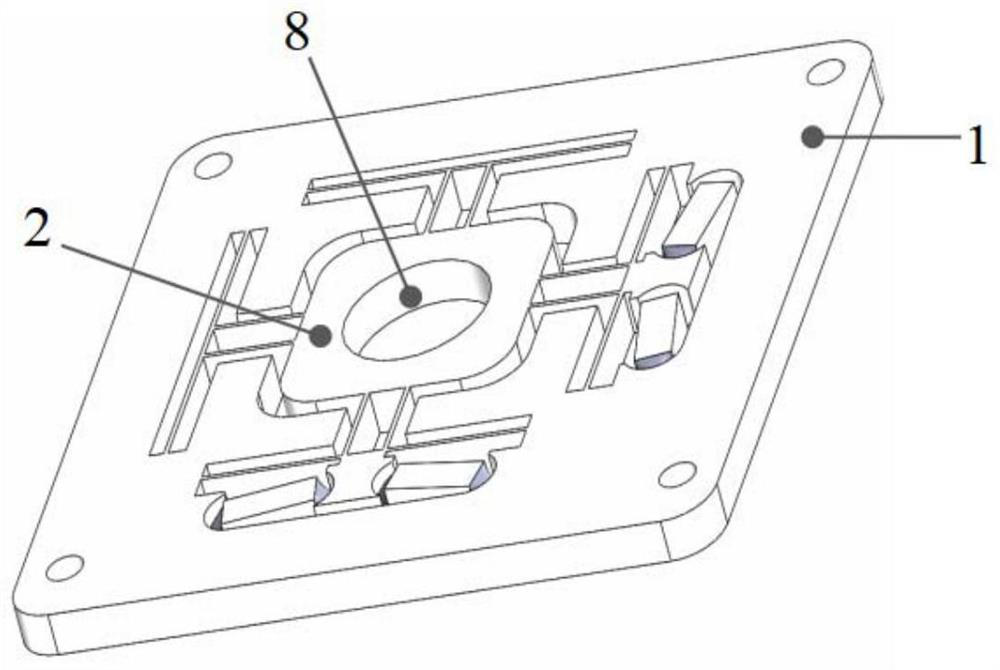
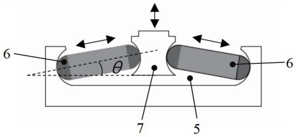
The invention provides a two-dimensional piezoelectric driving platform for inhibiting orthogonal disturbance, which comprises a substrate and a working platform, four groups of flexible isolation structures are arranged in an X-Y orthogonal plane by taking the center of the working platform as an original point, and the flexible isolation structures are connected with the working platform through a guide mechanism. Piezoelectric driving units are arranged on the sides, away from the working platform, of the orthogonal flexible isolation structures respectively, each piezoelectric driving unit comprises a U-shaped groove, two piezoelectric stacks and a center block, the U-shaped grooves are formed in the substrate and connected with the two ends of the flexible isolation structures, the center blocks are connected with the middles of the outer sides of the flexible isolation structures, and the two ends of each piezoelectric stack are provided with ball heads. The two ends of the piezoelectric stack abut against the inner side wall of the U-shaped groove and the side face of the center block respectively. The anti-disturbance capability of the piezoelectric driving unit is enhanced through the flexible isolation structure, and the situation that the piezoelectric driving unit in the X (Y) direction deflects and cannot work normally due to the fact that lateral force is brought to the piezoelectric driving unit in the Y (X) direction when the piezoelectric driving unit in the X (Y) direction works is avoided.

Description

technical field [0001] The invention relates to the technical field of parallel two-dimensional piezoelectric driving platforms, in particular to a two-dimensional piezoelectric driving platform that suppresses orthogonal disturbances. Background technique [0002] In the field of aerial imaging, due to the large relative velocity between the imaging system and the target, and the existence of the aircraft's own vibration, the imaging is blurred. At this stage, the clear and stable imaging of the imaging system can be achieved by adjusting the boresight of the optical lens in the optical system through the piezoelectric drive platform. [0003] Document [Optical Precision Engineering, 2017, 25(6): 1494-1501] discloses a two-way actuation large-stroke two-degree-of-freedom image stabilization mechanism, which connects piezoelectric drive units in two directions to a work platform through a flexible hinge , by synthesizing the displacement outputs in two vertical directions t...

Claims


Application Information

Patent Timeline
Patent Type & Authority Applications(China)
IPC IPC(8): H02N2/04
CPCH02N2/04
Inventor 黄卫清廉钧凯安大伟
Owner GUANGZHOU UNIVERSITY
Why Eureka
Eureka Blog
Learn More