Installation device and assembly method of transmission components

A technology for transmission components and installation devices, which is applied in the directions of transmission parts, rigid brackets of bearing components, bearing components, etc., can solve the problems of limited casing space, difficult to fix the outer ring of the bearing, and waste of space outside the casing. Achieving a wide range of effects

Active Publication Date: 2022-06-21
AECC HUNAN AVIATION POWERPLANT RES INST
View PDF0 Cites 0 Cited by
  • Summary
  • Abstract
  • Description
  • Claims
  • Application Information

AI Technical Summary

Problems solved by technology

[0004] The invention provides an installation device and an assembly method of a transmission assembly to solve the waste of space outside the casing caused by fixing the outer ring of the bearing on the outside of the casing when the transmission assembly is assembled in the casing from outside to inside , and when the transmission assembly is assembled in the casing from the inside to the outside, the space inside the casing is limited and it is difficult to fix the outer ring of the bearing

Method used


Image

  • Installation device and assembly method of transmission components
  • Installation device and assembly method of transmission components
  • Installation device and assembly method of transmission components

Examples


Embodiment Construction

[0026] The embodiments of the present invention will be described in detail below with reference to the accompanying drawings, but the present invention can be implemented in many different ways as defined and covered below.

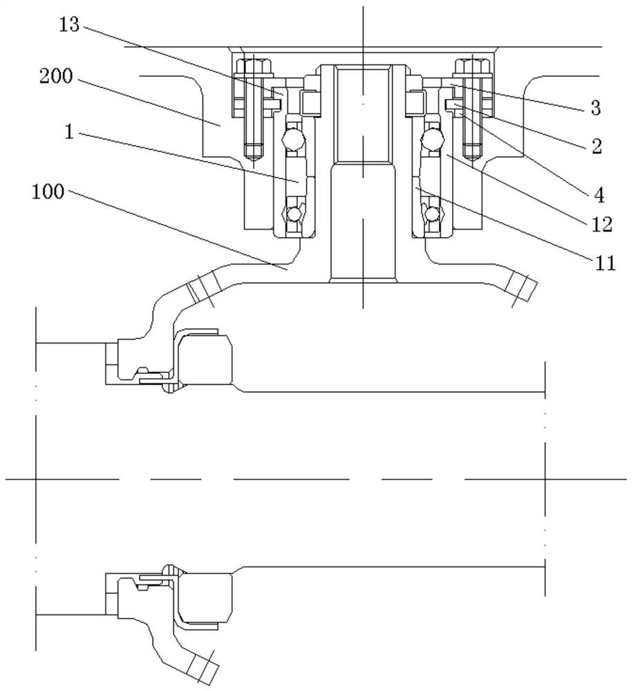
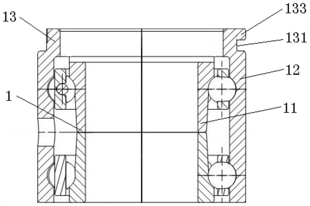
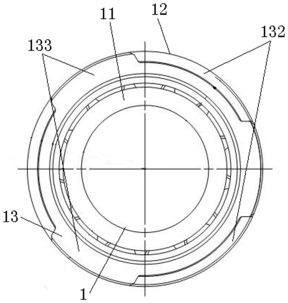
[0027] figure 1 It is a schematic structural diagram of the installation device of the transmission assembly according to the preferred embodiment of the present invention; figure 2 is the structural schematic diagram of the bearing of the preferred embodiment of the present invention; image 3 is the structural schematic diagram of the bearing of the preferred embodiment of the present invention; Figure 4 is the structural schematic diagram of the axial support plate of the preferred embodiment of the present invention; Figure 5 It is a schematic diagram of the structure of the anti-rotation pressing cover according to the preferred embodiment of the present invention.

[0028] like figure 1 As shown, the installation device of the transmission a...


PUM


Abstract

The invention discloses an installation device and an assembly method of a transmission assembly. The installation device includes a bearing, the inner ring of the bearing is connected with the transmission assembly, the outer ring of the bearing is fixed on the installation surface of the case, and the case is provided with a The casing hole, the mounting surface of the casing is located on the outside of the casing, the outer ring of the bearing is extended axially to form a mounting ring for extending from the casing through the casing hole to the outside of the casing, the outer diameter of the mounting ring Less than or equal to the outer diameter of the outer ring, the outer wall surface of the installation ring is provided with an axial positioning groove along the circumference, and the end surface of the installation ring is provided with a circumferential positioning block. The outer ring is fixed with a fixed anti-rotation mechanism. The fixed anti-rotation mechanism is inserted into the axial positioning groove, and the mounting ring is pressed axially and then fixed on the mounting surface, so as to realize the axial positioning of the bearing. At the same time, the fixed anti-rotation mechanism and The circumferential positioning blocks are matched to prevent the outer ring of the bearing from rotating in the circumferential direction.

Description

technical field [0001] The present invention relates to the technical field of aero-engines, and in particular, to an installation device and an assembly method of a transmission assembly. Background technique [0002] The development goal of advanced turboshaft turboprop engines is to improve the power-to-weight ratio, among which reducing the weight of the engine has become an important way to improve the power-to-weight ratio. Therefore, simplifying the structure of components and reducing the external dimensions have become one of the design goals. In some engine internal reducers, a driving bevel gear is often used to drive one or several driven bevel gears, and part of the power is separated from the main transmission chain to drive the engine accessories to work. Most of these driven bevel gears must be supported by cantilevers. The structure is supported by a set of double row angular contact ball bearings. The outer ring of the double row angular contact ball bearin...

Claims


Application Information

Patent Timeline
Patent Type & Authority Patents(China)
IPC IPC(8): F16H57/023F16H57/021F16C35/067
CPCF16H57/023F16H57/021F16C35/067
Inventor 王群刘飞明林碧华
Owner AECC HUNAN AVIATION POWERPLANT RES INST
Why Eureka
Try Eureka