Launch canister rear cover structure and mounting and using method

A technology of launching tube and cover structure, which is applied in the direction of launching device, etc., can solve the problems of unfavorable portable launch of individual soldiers, large recoil force, etc., and achieve the effects of simple structure, improved stability and high reliability.

Pending Publication Date: 2021-01-01
湖北航天飞行器研究所
View PDF0 Cites 2 Cited by
  • Summary
  • Abstract
  • Description
  • Claims
  • Application Information

AI Technical Summary

Problems solved by technology

When the space of the small-caliber missile launching tube is limited, the gas flow drainage channel should be released as much as possible to solve the problem that the recoil of the missile launch is too large, which is not conducive to the portable launch of the individual team, and can improve the stability of the missile's exiting attitude

Method used


Image

  • Launch canister rear cover structure and mounting and using method
  • Launch canister rear cover structure and mounting and using method

Examples


Embodiment Construction

[0021] In order to make the object, technical solution and advantages of the present invention clearer, the present invention will be further described in detail below in conjunction with the accompanying drawings and embodiments.

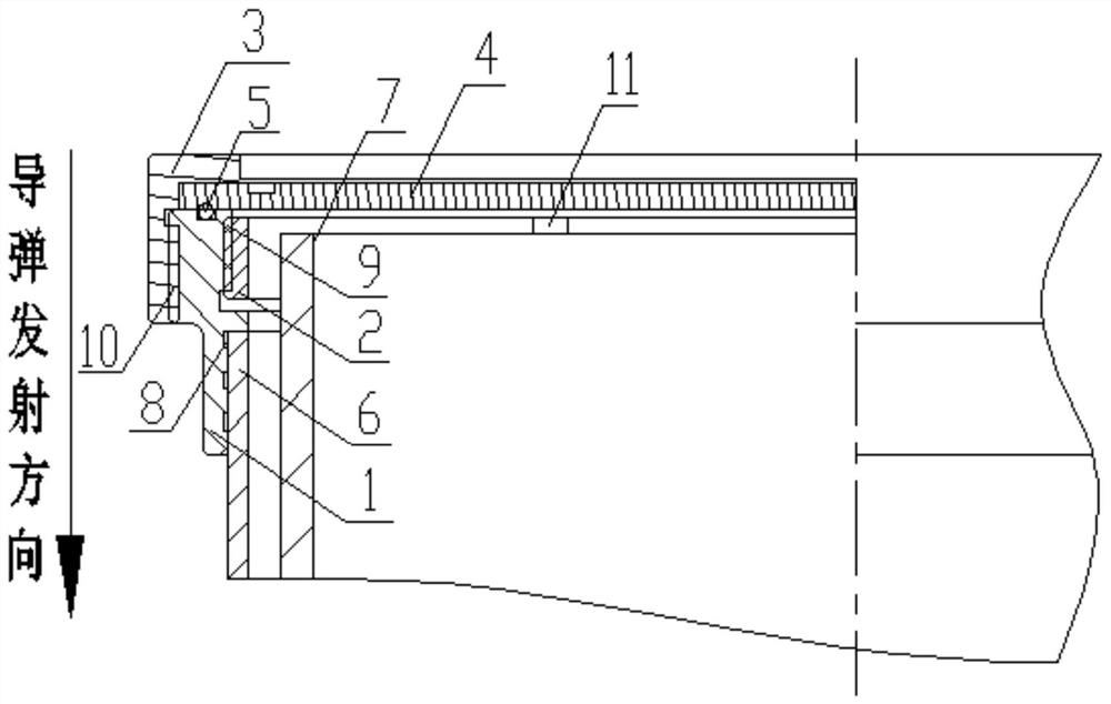
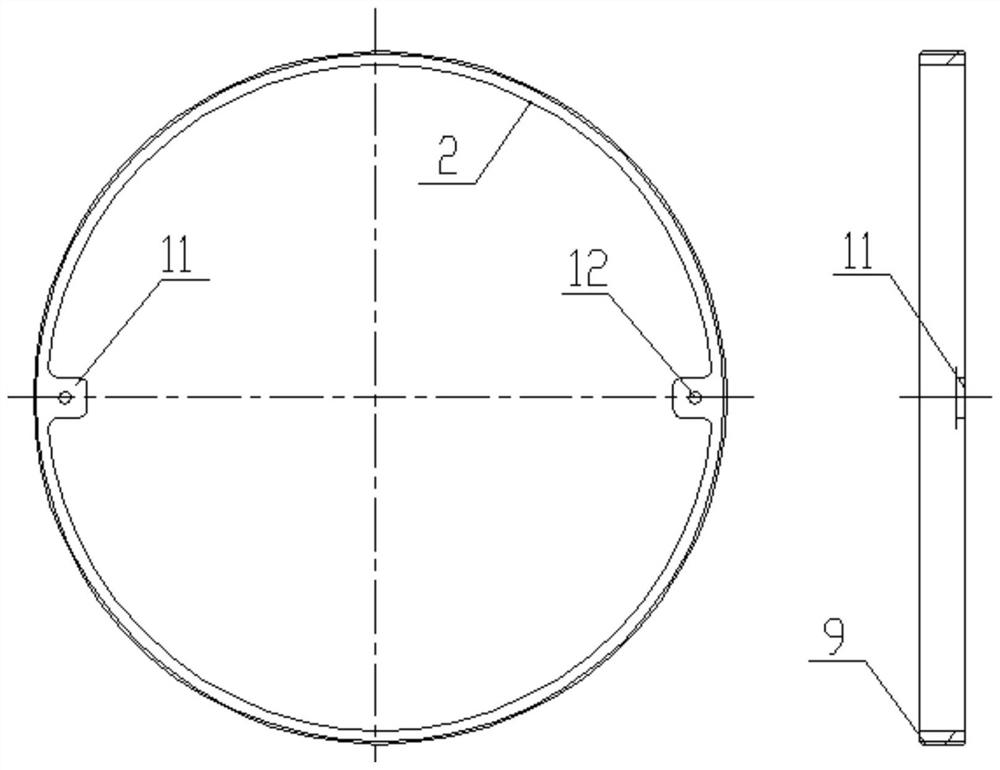
[0022] Such as figure 1 , figure 2 As shown, the embodiment of the present invention is a fragile launcher rear cover structure, including a rear end ring 1 , an inner pressure ring 2 , an outer pressure ring 3 , a fragile cover 4 and an O-ring 5 .

[0023] The rear end ring 1 is a concentric cylindrical ring structure, which is connected with the outer surface of the rear end of the launching cylinder 6 through the inner surface of the front end, and is bonded into one body with epoxy resin. Its bonding surface also has 3 rectangular surface annular grooves 8, (the rectangular surface annular groove 8 at the bonding surface place can have 2~5, in the present embodiment only with 3 rectangular surface annular grooves 8 as an example,) the rectan...


PUM


Abstract

The invention relates to a launch canister rear cover structure. The launch canister rear cover structure comprises a rear end ring, an inner pressing ring, an outer pressing ring, a fragile cover plate, an O-shaped sealing ring and the like. The rear end ring is of an internal and external double-thread structure, the internal thread is matched with the inner pressing ring, the external thread ismatched with the outer pressing ring, and the rear end ring is provided with the sealing ring. An axially adjustable limiting boss is arranged on the inner pressing ring, and the anti-loosening effect is achieved in cooperation with thread locking glue. The outer pressing ring is arranged on the outer ring of the rear end ring, and the outer pressing ring, the fragile cover plate and the O-shapedsealing ring form a sealing link. A weak link is engraved in the fragile cover plate and is broken through under the action of engine gas flow. The launch canister rear cover structure has the beneficial effects that a limiting mechanism is in threaded connection, has an axial adjustable function, can eliminate an assembly gap between a missile and a launch canister caused by machining errors andrealizes a reliable limiting function on the tail part of the missile; the engine gas flow is used as a fragile cover crushing power source, extra power is not needed, and the advantages of simple structure, low cost, high reliability and the like are achieved; the problem that the missile launching recoil force is too large, and portable launching by an individual soldier group is not facilitated is solved, and the stability of the missile launching posture is improved.

Description

technical field [0001] The invention belongs to the technical field of missile launching, and in particular relates to a structure, installation and use method of a launching tube rear cover. Background technique [0002] In the design process of the storage and transportation launch tube, the cylinder body, the cover, the orientation device and the locking mechanism are the key components, which directly affect the performance of the storage and transportation launch tube. The back cover is a kind of cover in the launch tube, which is installed at the tail of the launch tube. The design of the back cover requires good sealing at ordinary times, so that the built-in missiles are in a good storage environment and can be opened quickly when launching missiles. When the locking mechanism is to release the mechanical locking of the missile before launching, the design of the rear cover should also consider the function of limiting the position of the missile launched at an incl...

Claims


Application Information

Patent Timeline
Patent Type & Authority Applications(China)
IPC IPC(8): F41F1/00
CPCF41F1/00
Inventor 王力刘浩段相杰杨华周杰周哲赵亚运孙印锐
Owner 湖北航天飞行器研究所
Why Eureka
Try Eureka